release it.
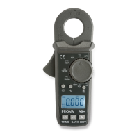
5. Frequency (Hz) Button
This button is used to measure frequency of ACA current in the ACA function.
6. Backlight Button
Press this button to turn the backlight on. Press it again to turn the backlight off.
The backlight will turn itself off automatically in 5 minutes.
7. Zero/Relative (
Δ
) Button
Once this
Δ
button is pressed in the ACA function, the current reading shall be
set to zero and be used as a zero reference value for all other subsequent
measurement. The button (ZERO symbol is displayed in the DCA function) is
also used to remove offset value caused by the residual magetism remained in
the core for the DCA measurement.
8. INR (In-Rush Current) button
Press this button to enter the in-rush current mode in ACA functions. For detailed,
please refer to the In-Rush Current Measurement of this manual.
9. LPF (Low Pass Filter) button
Press this button to enable low pass filter in the ACA functions. Once LPF is
enabled, the cut-off frequency (-3db) is set at 1 KHz.
10. LCD
This is a 3 3/4 digit Liquid Crystal Display with maximum indication of 3999.
Function symbols, units, bargraph, sign, decimal points, low battery symbols, and
zero symbol are included.
11. Low Battery Symbol
When this symbol appears, it means the battery voltage drops below the minimum
required voltage.
12. Data Hold (H), LPF, and Zero/Relative (
Δ
) Symbols
Once the corresponding function is enabled, the corresponding symbol appears
on LCD.
13. Units (K, Hz, and A) Symbols
Once a function is selected, corresponding current unit (A) or frequency (KHz)
shall be displayed on LCD.
14. INR symbol
Once the INR button is pressed, this symbol indicate In-Rush Current
Measurement is enabled.
15. 20 segments Bar-graph
Bar-graph has twenty segments correspond to 4000 counts of reading. It
displays segments proportional to the actual reading. Each segment represent
two hundred counts.
16. AC and DC symbols
The AC or DC symbol indicates the ACA or DCA function is selected.
17. Auto Power Off symbol