The ProVista ISC3042 is an MPPT (Maximum Power Point Tracking) solar system controller designed for use in PV (photovoltaic) systems to charge Lead-Acid type batteries. This includes SLA, VRLA, Lead-Calcium, AGM, and GEL battery types. The controller's primary function is to monitor the state of charge of the battery, control the charging process, and manage the connection and disconnection of loads. It ensures that the solar system operates at its maximum possible power by implementing the MPPT algorithm, which tracks the most efficient operating point of the solar panel to deliver the maximum available power to the battery.
Function Description:
The core function of the ISC3042 is to efficiently manage power flow from solar panels to batteries and connected loads. It continuously monitors the battery's charge level and adjusts the charging process accordingly. The controller employs advanced electronic circuits to harvest the maximum power from the solar panel(s), adapting to varying conditions such as temperature and solar irradiation levels.
The charging process involves three distinct stages:
- Bulk (Constant Current): In this initial stage, when the battery is in a low charge state, the controller delivers all available solar power to the battery system.
- Absorption (Constant Voltage): Once the battery reaches a certain voltage, the controller charges at a constant voltage. During this stage, the amount of current required to charge the battery gradually decreases. The constant voltage regulation prevents overheating and excessive battery out-gassing. This stage concludes when the battery charge current drops below 3 Amps or after 3 hours of absorption.
- Float (Maintenance): After the battery is fully charged, the controller reduces the voltage to a lower constant voltage setting to maintain the battery, also known as trickle charging.
The controller also incorporates a Night-Light Function (NLF) which allows for programmable load control for applications like street lighting. It recognizes day and night based on the solar array voltage, with NLF starting when the PV Input Voltage falls below 10 Volts.
Usage Features:
The ISC3042 offers several user-programmable and automatic features to optimize system performance and user convenience:
- Charging Voltage Programmability: The charging voltage is user-programmable, allowing for customization based on battery manufacturer recommendations. This includes adjustable Bulk and Float charge voltages.
- Load Terminal Switching: The load terminal switches on the positive side, simplifying wiring.
- Manual Load Switch with Automatic Re-start: Users can manually turn the load ON or OFF. If the battery falls below a specified voltage (11.0V/22V), the load output is disconnected to prevent excessive discharge. Once the voltage increases to 12.0V/24V, the load automatically reconnects.
- Night-Light Functions (NLF): This feature allows users to set two programmable timers for street light applications. The controller can be configured to turn the load ON for a specified duration (Timer1) and then turn it OFF after another specified duration (Timer2). If Timer2 hours are sufficient to reach dawn, the load will stay OFF for the remainder of the night; otherwise, it will turn ON again until dawn.
- MPPT Algorithm: The controller continuously performs the MPPT algorithm to harvest the maximum power available from the solar panel, ensuring efficient energy conversion.
- Temperature Compensation: The ISC3042 has an internal ambient temperature sensor that compensates during the float mode, automatically adjusting the float voltage based on ambient temperature (e.g., varying voltage ranges for different temperature brackets for 12V and 24V systems). This function is active when the float voltage setup is set to "OFF" for automatic adjustment.
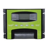
- Display and Operation: The device features an LCD display that shows a variety of system data using symbols and digits. Four buttons (Page Down, Enter, Page Up, Menu) control all settings and display windows.
- The default display shows battery voltage/capacity.
- Pressing the "Menu" button cycles through displays for charging current, load current, system time, Bulk voltage setting, Float voltage setting, NLF setup, Timer1, and Timer2.
- The "Enter" button is used to confirm settings in program mode and also functions as a manual load switch (ON/OFF) in the default display mode.
- "Page Up" and "Page Down" buttons are used to adjust numerical values during programming (e.g., hours for timers, voltage settings).
- 5V USB Output: The controller provides a 5Vdc/500mA power supply via a USB output, useful for charging small electronic devices.
Maintenance Features:
The ISC3042 is designed to be maintenance-free. However, regular checks are recommended to ensure optimal performance and longevity of the PV system:
- Annual System Check: It is strongly suggested that all components of the PV system be checked at least annually.
- Ventilation: Ensure adequate ventilation of the cooling element to prevent overheating.
- Cable Integrity: Check the cable strain relief and ensure that all cable connections are secure.
- Tightening Screws: Tighten screws if necessary to maintain secure connections.
- Terminal Corrosion: Inspect for and address any terminal corrosion.
Protection Functions:
The controller includes comprehensive protection functions to safeguard the battery, solar panel, and loads, and to ensure safe operation:
- Overcharge Protection: Prevents the battery from being overcharged, extending its lifespan.
- Deep Discharge Protection: Disconnects the load if the battery voltage falls below a specified level (11.0V/22V) to prevent irreversible damage to the battery.
- Battery Under-voltage Protection: Similar to deep discharge protection, it safeguards the battery from operating at dangerously low voltages.
- Solar Panel Reverse Current Protection: Prevents current from flowing back into the solar panels at night, which could drain the battery.
- Reverse Polarity Protection: Protects against incorrect wiring of the load, panel, and battery.
- Automatic Electronic Fuse: Provides protection against electrical faults.
- Short Circuit Protection: Protects the load and panel from damage due to short circuits.
- Over Voltage Protection at Panel Input: Safeguards the controller from excessive voltage from the solar panels.
- Open Circuit Protection without Battery: Allows the controller to operate safely even if the battery is not connected.
- Overload Protection: Prevents damage from excessive current draw by the load.
- Battery Over Voltage Shutdown: Shuts down the system if the battery voltage exceeds a safe limit.
The controller is designed to recover from common installation faults without permanent damage. After correcting a fault, the device will resume normal operation. Error codes are displayed on the LCD to indicate specific malfunctions, with higher priority errors displayed first. Examples of error codes include:
- E1 (Battery reverse polarity warning): Remedy by reconnecting the battery correctly.
- E2 (Battery Voltage too high or too low): Remedy by checking battery voltage, manually recharging if too low, or replacing the battery if it cannot be recharged.
- E3 (Module current too high): Remedy by reducing the input current (module power) to below 30 Amps.
- E4 (Over current at the load output): Remedy by reducing load current to below 30 Amps. If the issue persists, a reset procedure involving disconnecting and reconnecting terminals in a specific sequence is provided.
Installation Guidelines:
- Install in a ventilated area, away from flammable materials.
- Mount on a solid, even, dry, and non-flammable surface.
- Keep battery-to-controller cables as short as possible (1-2 meters ideal) and of suitable diameter to minimize voltage loss.
- Install indoors or in a protected manner to shield from humidity, dripping, rainwater, and direct/indirect heat.
- Ensure 15cm free space on each side for air circulation.
- Protect the LCD display from UV rays to prevent discoloration.
- Installation should be performed by trained personnel in accordance with regulations.
- Follow installation instructions for all PV system components.
- Ensure cables are undamaged and polarity is correct. Use insulated tools.
- The ISC3042 can handle input voltage up to 65 V DC. For high voltage installations, the entire solar energy system must be installed with protection class II. Cover solar modules during installation.
- Grounding is not technically required for standalone systems, but common grounding of the negative battery and load control output is acceptable for negative earth electrical systems (e.g., caravans). The ISC3042 grounds the negative only; the PV array output should NOT be grounded.
- Connect wires in a specific sequence (1 to 6) and disconnect in reverse (6 to 1).
- The controller automatically detects 12V or 24V battery banks.
- Do not exceed nominal ratings.
- Suggested cable lengths are provided for solar panel, battery, and load connections.