main board and instead stays attached to the gray plastic support. The Oscillator board in the P600 and
P1200 is held in place with screws and will not come out after the top cover has been removed.
8. REMOVING THE OLD OSCILLATOR CARD ON THE P300
a. If the oscillator card remains attached to the gray support on the bottom cover:
Simply remove the Card from the support and set it aside. You will be sending this old Oscillator Card back
to PS Audio in the postage paid box (US residents).
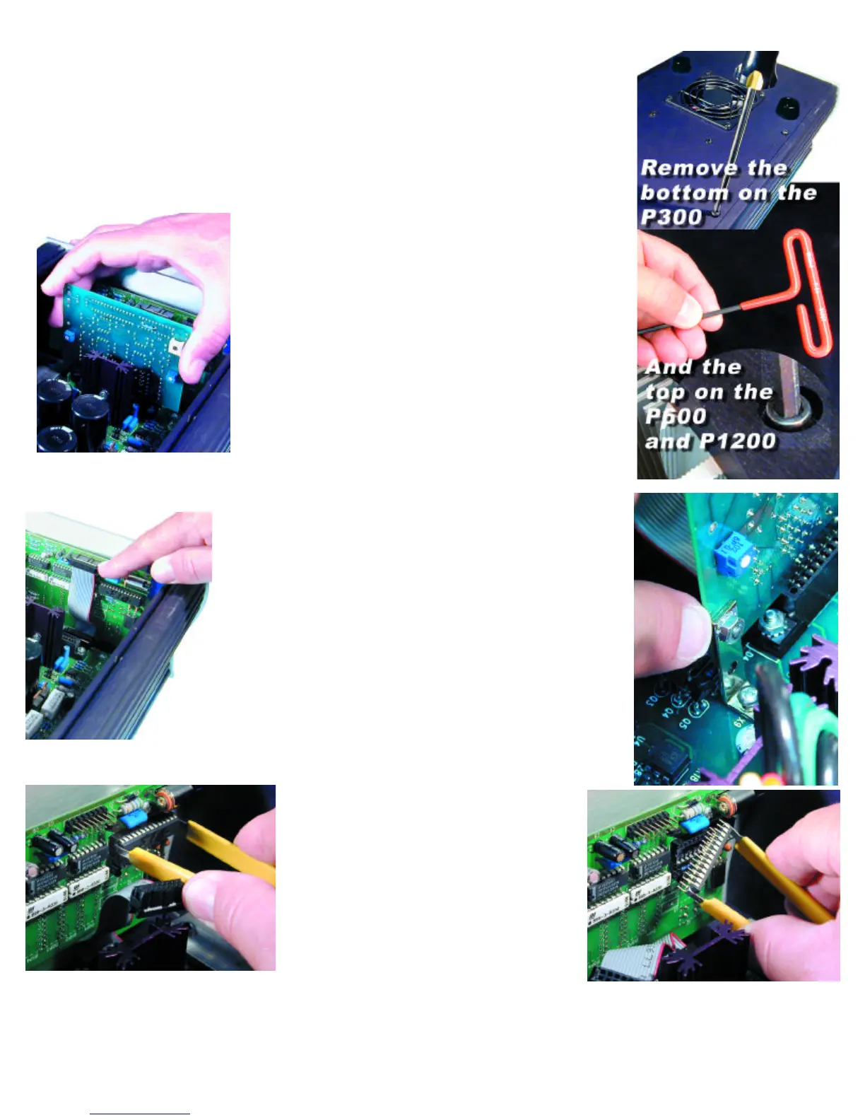
b. If the oscillator card remains attached to the motherboard:
Simply grab the card with two fingers and lift straight up to remove. Do not rock the card back and forth to
remove it! Set it aside. You will be sending this old Oscillator Card back to PS Audio in the postage
paid box (US residents).
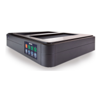
9. Removing the oscillator card on the P600 and P1200.
Remove the two screws and nuts holding the oscillator board in its
socket. Then, Simply grab the card with two fingers and lift straight up
to remove. Do not rock the card back and forth to remove it! Set
it aside.
You will be sending this old Oscillator Card back to PS Audio in the
postage paid box (US residents).
10. Replacing the front panel microprocessor “chip”.
First, we need to take out the Old Microprocessor Chip.
a. This is the part that takes a little patience and concentration. You
are going to remove the front panel microprocessor chip and replace
it with a new one.
b. First locate the Front Panel Board. This is the small computer board
that is screwed to the back of the Power Plant's Front Panel.
c. Next, unplug the small cable on the Front Panel Boardthat connects to the Power Plant's main board.
This takes your attention, but must be done before you can remove and replace the Front Panel
Microprocessor.
d. The Connecting Cable is flat and gray, with a rectangular black con-
nector. Using your thumb and forefinger, pull the connector of the
Connecting Cable off the Front Panel Board.
e. Next, locate the Microprocessor on the Front Panel Board. The
Microprocessor is the only computer chip on the Front Panel Board that
is in a socket.
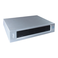
f. Next, take the Chip Puller enclosed. The Chip Puller will be used to
carefully pry out the oldMicroprocessor. Notice the Chip Puller has two
small prongs.
g. Put the two prongs of the Chip Puller between the Chip and the sock-
et on the left and right side. There is a small gap between the Chip and
the socket for you to get in the prongs of the Chip Puller. It may take a
little wiggling of the Chip Puller to get its prongs under the Chip.
h. Next, squeeze the Chip Puller together and pull the Microprocessor
Chip straight out of its Socket. It may take a tug. Pull straight back. When
the OLD Microprocessor chip pops out of its Socket, lay it out of the
way.
Great work! You are almost done. Take a break.
Next, we need to install the New Front Panel
Microprocessor Chip. Carefully open the sealed
end of the pink bubble wrap bag.
Do not take out or touch the microprocessor chip
yet.
Just open the pink bag. You MUST first make sure
you have discharged all static from yourself. This is
not difficult. The easiest way of doing that is to touch
a metal object. A metal table or chair leg is good. Or
an exposed metal part of some appliance that is plugged into the wall, such as the table lamp you
should have lighting your work area.
i. After you have discharged yourself of any static electricity, carefully remove the new Processor Chip from the pink bag. The Chip is pressed
to a small piece of black conductive foam. This special foam protects the Chip from static.
Do not remove the chip from the anti static foam yet.