PS Engineering
PMA4000 Series Audio Selector Panel and Intercom System
Installation Manual
200-041-0002 Page iii Rev 5, March 2007
3.3.5 Internal Recorder System (Part number 11941, only) ................................. 3-4
Section IV- Warranty and Service ........................................................................... 4-1
4.1 Warranty .......................................................................................................... 4-1
4.2 Factory Service ................................................................................................ 4-1
Appendix A External PTT Hook Up..........................................................................A
Appendix B- Installation Drawing and Connector Layout.......................................B
Appendix C Unit Connector Wiring ...........................................................................C
Appendix D -Instructions for FAA Form 337 and Continuing Airworthiness .......D
Appendix E RTCA DO160D (EUROCAE ED-14) Environmental Qualification
Form ...................................................................................................................................E
Table of Figures
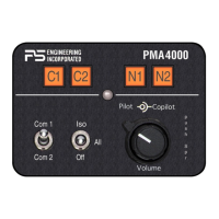
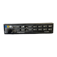
Figure 1-1 PMA4000 ....................................................................................................... 1-1
Figure 3-1 PMA4000 ....................................................................................................... 3-1
Figure 3-2 Mic Selector ................................................................................................... 3-2
Figure 6-1- Hole Configuration ..........................................................................................A
Figure 6-2 Hole Configuration to avoid rectangular cutouts..............................................A
Figure 6-3 Connector Layout..............................................................................................B
Figure 6-4 Installation Diagram..........................................................................................B
Table of Tables
Table 3-1 Mic Muff ™ Part Numbers ............................................................................. 3-3
Table 3-1 Intercom Modes............................................................................................... 3-4
Revision History
Rev. By Date Description of Change
3 Picou January 2006 Updated section 2.4.4 for power
wires, allow smaller gage.
4 Picou March2006 Added information for 11941
5 Picou March2007 Clarified mounting dimensions