PS Engineering
PMA7000M-S Series Audio Selector Panel and Intercom System
Installation and Operator’s Manual
200-070-0006 Page 2-7 Rev. 6, Nov 98
2.4.14 IRS Installation (Option 1, and 2)
To install the IRS, a momentary push button switch is required. This switch can be located
any where in cockpit convenient to the pilot's reach. The switch must be connected to pin
19 of J2 of the PMA7000M-S.
2.4.15 Audio Message Installation (Option 1 and 2 only)
The audio message installation requires inputs from an external annunciator, such as an
Electronics International engine gage system. A falling edge (input pulled low) when ap-
plied to the appropriate pin of the connector will cause the message to be played, repeat-
ing every two seconds, until the acknowledge (“ACK”) button is pushed.
Install the “ACK” button in a location convenient to the pilot and copilot position. This
switch is a momentary SPST switch between J2 Pin W and ground.
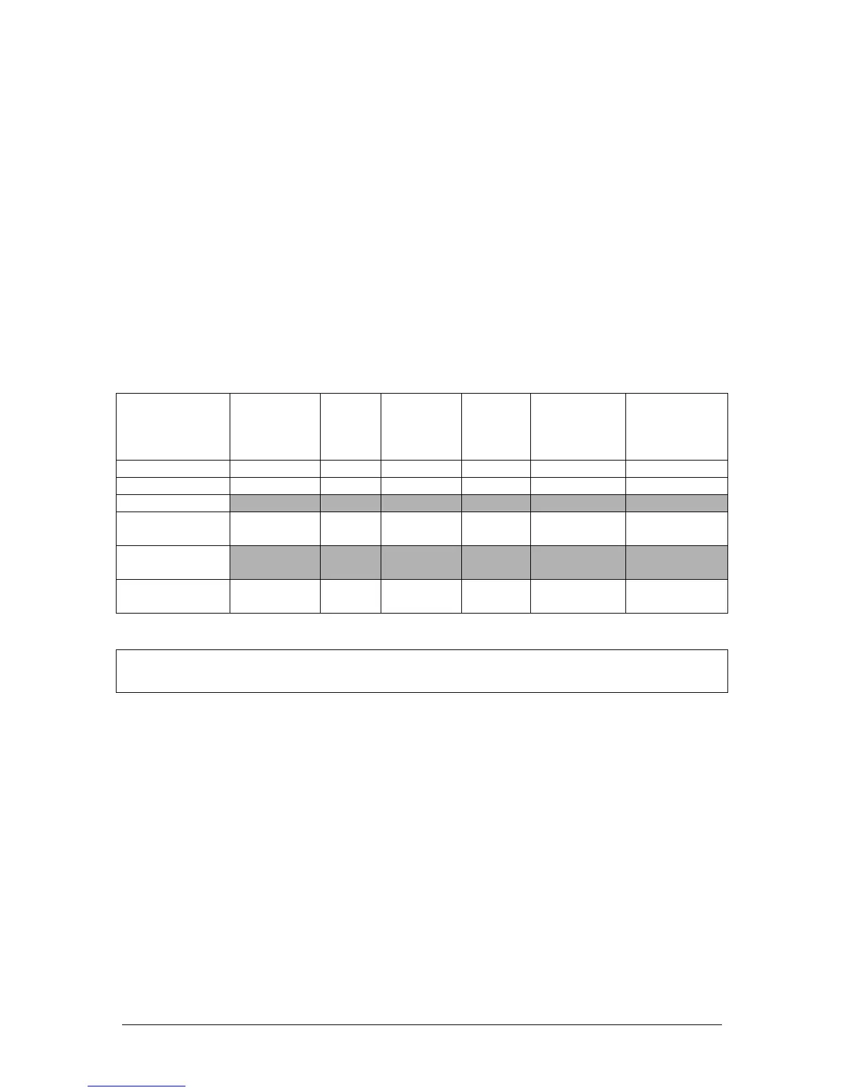
The following table contains information regarding various inputs.
Function EGT or CHT Fuel
Flow or
Level
Oil Pres-
sure or
tempera-
ture
Volt/
Amp
RPM Manifold
Pressure
PMA7000 Pin Z 22 Y 21 X 20
Message Number 1 2 3 4 5 6
Option 1
Message Text “Check tem-
perature”
“Check
fuel”
“Check
oil”
“Check
battery”
“Check en-
gine speed”
“Check boost”
OPTION 2
Function
Vista Map
System
CHT Cooling
Message Text “Check tem-
perature”
“Check
fuel”
“Check
oil”
“Check
battery”
“Check Vista
Map”
“Shock Cool”
Other combinations can be created at additional cost.
NOTE: PS Engineering can only provide input information at this time. Approval basis is
the responsibility of the installer. Contact PS Engineering for more information.
2.5 Marker Installation (PMA7000M-S)
The marker beacon receiver is an option included in the PMA7000M-S. Non-marker
(PMA7000S) units can provide audio interface with the external receiver (see section
2.5.4).
2.5.1 Middle Marker Sense
A Middle Marker sense output signal is available from the 7000M-S to flight control sys-
tems. This function will not operate during the test mode. This output will go to +4.7
VDC (± 0.5 VDC) when a valid Middle Marker signal is received. This output is J1, pin 2.