26 27
Step 3
Is the voltage at the VP, connector P1 pins 1 & 3, greater than 18 Volts?
(Use a volt meter to measure the voltage).
Yes – Voltage is too high, check power supply and retest
No – Proceed to step 4
NOTE: Create a voltage map of the site by sketching out the locations of every
AI device on the site. Use a multimeter to take DC power readings at each device.
Note these readings on the sketch. Any device that is receiving less than 12V is
underpowered and can cause the entire system to lock up.
Step 4
Is the display on the VP blank?
Yes – Replace the VP and retest
No – Proceed to step 5
Step 5
Is the VP communicating with the controller and software?
Yes – Contact Technical Support if the VP is still not working.
No – Check wiring and proceed to step 6
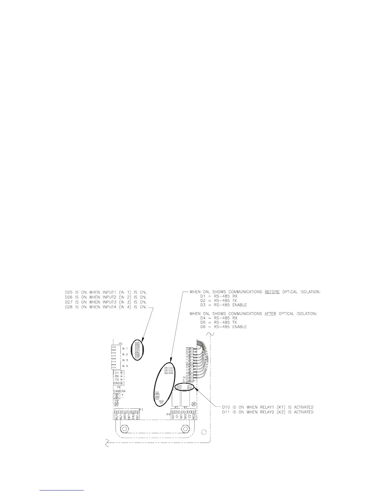
This can be determined by checking the LEDs on the VP board or
by running the system setup report on the controller. When the VP is
communicating with the controller, LEDs D5 and D4 will be blinking. If
neither of the LEDs are blinking, proceed to step 7. See Figure 18 for the
location and function of the LEDs.
Figure 18