72-910-02
REV. P
8
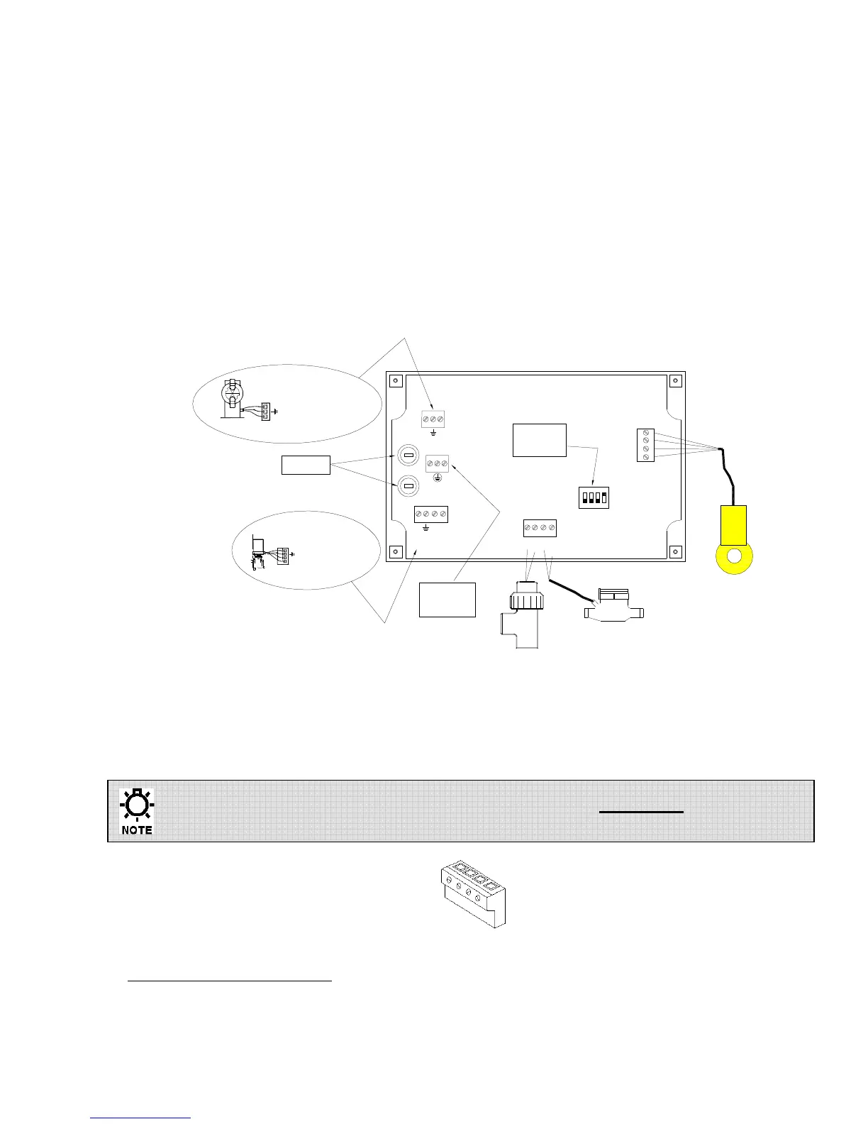
Bleed (solenoid valve)
This control output is identified on the controller PC board as location PL5. The terminal
block connections for PL5 are HOT (LINE), RTN (return or Neutral), and Ground.
This control output will energize when the programmed conductivity set point is exceeded.
This output will de-energize when the conductivity reading falls below the set point minus
the fixed set point differential (-5% of set point).
Conductivity Probe
The controller is supplied with one temperature compensated conductivity sensor. The
sensor connects to PL1 of the controller PC board. Match the wire color from the probe with
the text next to connector PL1.
DOSE
PL4
RET
HOT
no HOT
F1
5A
SUPPLY
PL3
RET HOT
RET
nc HOT
PL5
BLEED
F2
5A
COM
FLOW
COM
WATER
METER
BLACK
BROWN
ORANGE
RED
CONDUCTIVITY
SENSOR
1 2 3 4
ON
DIP
SW1
PL2
FLOW
SWITCH
CONTACT
METER
TOROIDAL
PROBE
HOTRET
HOT
RET
MOTORIZED BALL VALVE
(RETURN / NEUTRAL)
(EARTH / CHASSIS GROUND)
(NORMALLY / OPEN)
(NORMALLY / CLOSED)
FUSES
SUPPLY
POWER
DIP
SWITCH
PUMP
(3-WIRE)
PL1
(NORMALLY OPEN)
(EARTH / CHASSIS GROUND)
(RETURN/NEUTRAL)
(4-WIRE)
Fig. 3: Wire Connections
3
These connections are made using a green terminal block that uses screws to retain a wire inserted
into the square openings as seen below. Using a small flat head insulated screwdriver, loosen the
screw enough to allow clearance for the wire, then insert the wire and tighten the screw securely.
Controllers without an external flow detection switch must have a jumper
installed across the flow switch input, PL2 (see Fig.3).
Fig. 4: Terminal Block
3
Trained service personnel are required for all electrical connections. This product does not contain operator serviceable
parts.