72-910-02
REV. P
9
4. System Operation
B
EFORE APPLYING POWER
,
INSURE THAT DEVICES BEING CONTROLLED BY THIS
CONTROLLER ARE NOT IN A POSITION TO CAUSE HARM OR DAMAGE IF ENERGIZED UPON
INITIAL START
-
UP
.
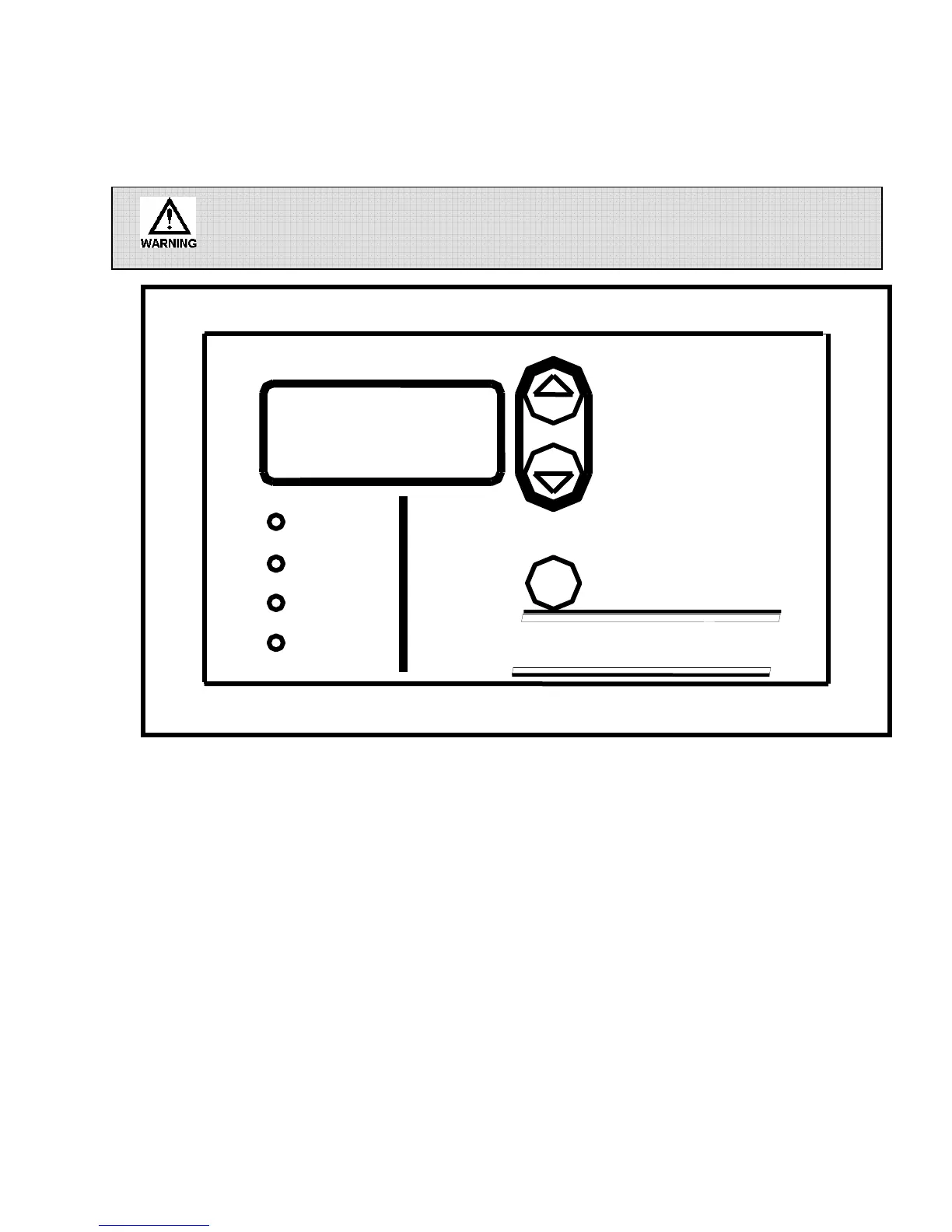
Front panel
Fig. 5
4.1 Front Panel
The front panel of the controller has a 4-digit LCD display, four LED indicators, and three
pushbuttons that are used for programming and controller monitoring.
The LCD display is used to display the system conductivity as well as various system parameters
during programming. The LED’s are used to indicate what mode or function the controller is
operating in. The m (MODE) button is used to enter programming mode and to view the controller
parameters. The up and down arrows are used to change the controller settings once in programming
mode.
DISPLAY
SCREEN
m
MICROtrac
Bleed
uS
Set Point
Feed