DMX In/Thru 5 Pin XLR Connectors
Digital Control Signals:
DMX SIGNAL
4 PIN XLR Low Voltage and DMX Output Socket
ChromaZone12
ChromaZone12NP
ChromaZone12
ChromaZone12
ChromaMR16 ChromaPoint
ChromaZone12NPs
ChromaZone12
ChromaZoneNPs
ChromaMR16 ChromaZoneNPs
ChromaPoints
ChromaZone12
-+
5 Pole Wago Output sockets:
ChromaFixtures
ChromaFlex cable
ChromaFlex
ChromaZone ChromaFixture
Wiring:
ChromaFlex
Two 5 pin XLR sockets (in/thru) are
provided. The pin connections of the sockets are:
From March 2008 a 4 pin XLR output socket is fitted to the
. This can provide 24VDC Low Voltage Power
and DMX to feed a (No Power) and may be
used when the is not fully loaded to its 200W
limit.
This is the most economical control solution when many low
power fixtures are to be driven with individual DMX control, for
example in Low Resolution Video displays.
The standard can power up to five
fittings per output or up to 12
fixtures, but all the fixtures on one output would do the same thing.
Now, a number of and low power fittings
may be "slaved" from one powered until its
power limit of 200W is reached. E.g. up to 4
and 60 fixtures, or 11 and 144
could be connected to one powered
- all individually controllable.
The pin connections of the 4 Pin XLR socket are as follows:
LV POWER: Pin 1 = 0V / Chassis Earth Pin 4 = +24VDC
DMX SIGNAL: Pin 2 = Signal Pin 3 = Signal
XLR4 "Scroller Cables" are used for interconnection.
6/12 five pole grey connectors
are provided on the side of the zone, these represent the 6/12
output channels. Each connector provides the necessary power
and signal to drive a ChromaFixture.
Two Connectors are supplied with many of the .
is available from Pulsar.
It is recommended that the maximum run of
between the and a is 20m.
Strip back the outer insulation and the insulation from the
cores of the a suitable distance. Insert a flat blade
screwdriver into the cage clamp connector and press it down to
open the terminal. Insert the wire. Release the screwdriver. The
spring loaded cage clamp holds the wire tightly ensuring a long
term, reliable connection.
PIN No. Function
ChromaFlex
Core Colour
0V
1
2
3
4
Red 0-10V
Black
Green 0-10V
Blue 0-10V
Red
Green
Blue
White
+24Vdc
5
Failure of the
usually indicates an internal fault requiring servicing by a
qualified engineer.
Each 24VDC output is protected by an internal, resettable solid
state fuse. Switch off the unit, fix the fault and switch on again to
reset the fuse.
The 0-10V signal inputs and outputs are protected against shorts
to 24V, 0V and static damage.
ChromaZone Electronics 5 Amp, HRC, 5x20mm
Fuse,
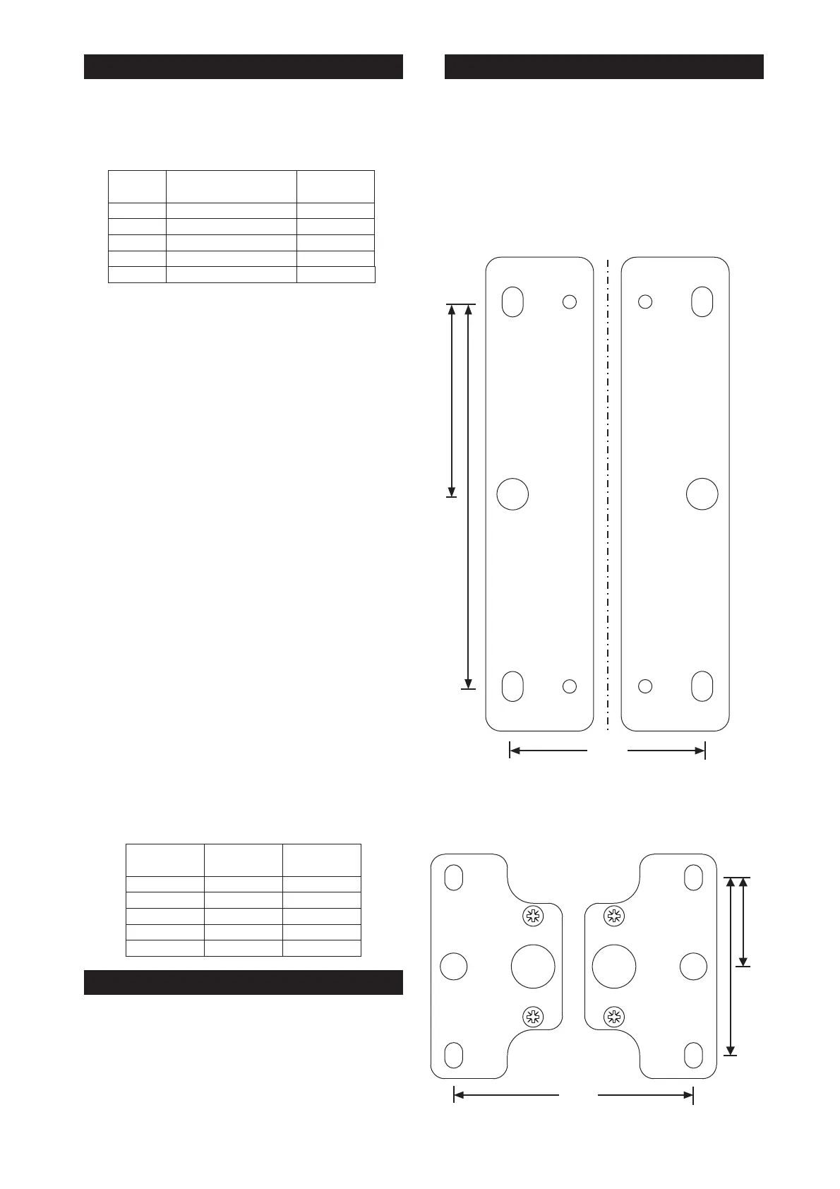
The may be wall or ceiling mounted using the
2 x mounting plates which are supplied and are located on the
underside of the tray. Remove the 4 x M4 countersunk posipan
screws, rotate the fixing brackets 180 deg and re-fix to the tray
using the same screws.Avoid over tightening the screws when re-
locating them into the tray.
The image shows the fixing brackets with their
dimensions as if they are fitted to the respective tray.
An M6 hexsert can be found near the mains switch, (location also
shown on artwork), this has been installed for use with a Safety
chain.
CZ6/12
CZ6/12
128.0
64.0
304.0
The may also be truss mounted using the M10
nutserts, two are located on the side of the tray and one can be
located on the top of the tray. Ensure you do not over tighten the
fixings in to the tray.
ChromaZone12
250.0
35.0
70.0
The may also be truss mounted using the M10
nutserts, the two M10 Nutserts can be located on the base of the
unit. Ensure you do not over tighten the fixings in to the tray.
ChromaZone6
CZ6 & CZ12 SIGNALS AND CONNECTIONS CZ6 & CZ12 MOUNTING
FUSES AND PRECAUTIONS
PIN No. Function
Pulsar DMX
Cable Colours
Screen-Chassis Earth
1
2
3
4
DATA -
Screen
DATA +
no connection
Blue
White
Green
Red
LVS +24VDC (male only)
5

 Loading...