The may be wall or ceiling mounted using the
2 x mounting plates which are supplied and are located on the
underside of the Enclosure. The fixing brackets are not to be
removed from the enclosure.
The image above shows the fixing brackets with
their dimensions as if they are fitted to the respective enclosure.
CZ12-200IP
CZ12-200IP
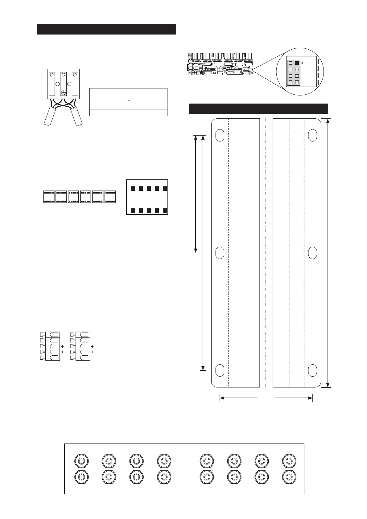
Mains Wiring:
5 Pole Wago Output Connection Blocks: 6 Double
Orange
ChromaFlex
ChromaZone ChromaFixture
ChromaFlex
DMX SIGNAL:
OUTPUT GLANDS:
A Wago 294 series Mains in / Thru connector is
provided inside the enclosure. Wiring details are shown below.
AMaximum of 2 x 1.5mm cores can be put in to each terminal.
five pole
connectors are provided inside the enclosure, these
represent the 12 output channels. Each connector provides the
necessary power and signal to drive a ChromaFixture.
Shown above are all the output connectors if looking in to the
product from above. The ChromaConnectors will need to be
removed from any ChromaFixture before installing in to the Zone.
It is recommended that the maximum run of
between the and a is 20m.
Strip back the outer insulation and the insulation from the cores of
the a suitable distance. Insert a flat blade
screwdriver into the cage clamp connector and press it down to
open the terminal. Insert the wire. Release the screwdriver. The
spring loaded cage clamp holds the wire tightly ensuring a long
term, reliable connection.
The DMX Digital Control Signals are explained on page 1 & 2.
The DMX connector wiring for an IP Zone is shown below:
16 x M12 Liquid tight Glands are supplied. 12 are for the channel
outputs, 2 are for the Mains In/Thru and 2 for DMX In/Thru. A
Printed legend can be located on the outside of the enclosure.
This is a guide to aid you in the installation of the glands.
Drill a 14.0mm hole and tap to M16x1.5mm. Alternately drill a
hole to the size of 16.0mm and fix using the Gland Nut. When
installing the M12 Glands, ensure the Liquid Tight O-Ring is
placed on the gland before inserting gland in to enclosure.
When replacing the lid, please ensure no debris of any kind is
inside or around the seal of the lid before re-installing.
LN
MAINS IN / THRU
MAX - 2x1.5mm Cables
in each terminal
Cable Colours
Green/Yellow =
Brown =
Blue =
Earth / Ground
Live / Phase / Hot
Neutral
BOTTOM ROW
TOP ROW
13579
11
2468
10 12
BLACK
0V
BGR
+24V
BLUE
GREEN
RED
WHITE
0V
DATA
NC
LVS
NC
0V
DATA
NC
DMX IN DMX THRU
(AS VIEWED ON PCB)
The Grey Wago connectors
as viewed on PCB and shown
in the artwork on the inside
of the lid.
195.0
97.5
304.0
223.0
The can be set up by plugging a UIM Remote (User
Interface Module Remote) in to the PCB mounted header (shown
below). When set up is complete ensure the enclosure lid seal is
seated correctly and the lid screwed down securely.
CZ12-200IP
CZ12 - 200IP MOUNTING
CZ12 - 200 SIGNALS AND CONNECTIONSIP
CABLE GLANDS
GLAND (PULSAR PART 4562)
DRILL HOLE - 14.0MM
TAP HOLE - M16 X 1.5MM
BEFORE INSTALLING
ENSURE LIQUID TIGHT O-RING
IS PLACED ON GLAND
DMX IN
1
DMX THRU
2
MAINS IN
MAINS THRU
3
4
5
6
7
8
9
10
11
12
The top right pin is missing from the
PCB mounted header, this is to ensure
polarity is observed when plugging the
socket in for setup.
+5V
SCL
SDA
0V
Missing
pin

 Loading...