EN
21
2. It has two working modes - Mode 1 (the switch-on pressure can be set - the pump switches off when the
maximum delivery height of the pump is reached) and Mode 2 (the switch-on and switch-off pressure can
be set)
3. It has a pressure protection function.
4. It has an overload protection function.
5. Has a protection function in case of frequent pump switching
6. It has an enforceable pump start function to prevent the pump from jamming due to long periods of
inactivity.
7. It has the function of automatically stopping the pump in case of water shortage and restarting it.
8. The switching pressure setting range is large, the differential pressure is small, and the requirements for
the maximum delivery height of the pump are low.
9. The unit can be installed horizontally on the pump.
5 Installation
1. Installation and maintenance of the unit must be carried
out by qualified personnel who are familiar with this
manual.
2. This product can only be used for clean water;
therefore, the user should check the water in the piping
system prior to installation. If the water contains iron ore
and iron oxides, the pressure control will fail after a
period of time.
3. The user should fit the pump suction with a check valve.
Before installing the unit, test the pump to make sure it
does not show any problems.
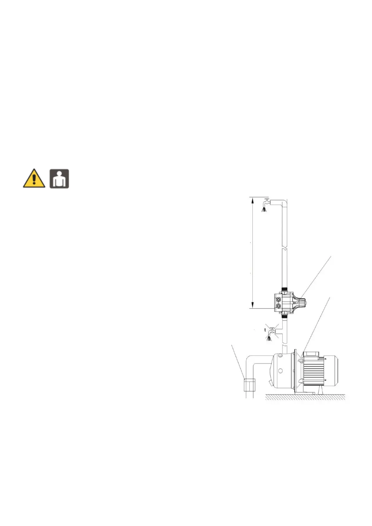
4. The unit must be installed directly on the pump delivery
and the direction of water flow must match the direction
of the arrow shown on the unit. The user should use a
pipe to connect the outlet of the unit.
5. Do not leave any foreign objects inside the unit to
prevent damage and failure.
6. The unit must be horizontal when installed and the
distance between the highest position of the tap and the
unit must not exceed X metres. (See diagram 2 for
details.) Installation is shown in diagram 1, wiring is
described in diagram 3