3 (13)
SERVICE INSTRUCTION
K 82, 85, 101, 102, 104, 151, 155
K82/85/101/102/104/151/155.58.0211.Eng/Digital
Data plate information
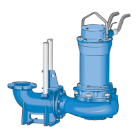
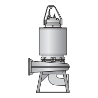
Pump design
The design of the pump features high reliability and easy main-
tenance. The major parts of the pump are few in numbers and
do not require special tools during disassembly and assembly.
The electric driving unit consist of Stator Unit (Stator and Stator
Housing), Rotor Unit (Rotor, Shaft and Bearings), Impeller, Oil
Housing, Mechanical Shaft Seal Unit and Junction Box
(Junction Box Cover, Terminal Board and Cable Entries).
An exchange system is used for the Stator Unit and Mechanical
Shaft Seal Unit.
Box 5207 S - 12116 JOHANNESHOV SWEDEN
5
6
7
8
9
1
2
3
4
K 80
No 99999999 P.2 2.0 kW
3 Ph 50 Hz
U 400 V Y n 1385 rpm Class F IP68
I 5,4 A 98 kg
20 m
1 Type of pump
2 Serial number
3 Working voltage
4 Rated current
5 Rated output
6 Engine speed
7 Frequency
8 Winding class
9 Weight
A Type of pump
B Serial number
C Working voltage
D Rated current
E Rated output
F Cos ϕ
G Frequency
H Head
I Speed