TM
Locating Blower Pack
The distance that visible steam will travel after leaving the Blower Pack is dependent upon the relative humidity in the room
and the capacity of the humidifi er. If this visible steam comes in contact with any solid object (walls, beams, machinery, etc.)
it may form condensate and drip. Refer to Fig. 3 (Fig. 3 is located on page 11) and Table 4 for data on visible steam travel.
This will aid you in planning the location of the Blower Pack.
Blower Pack
Visible Steam
Rise & Throw
Humidifi er Model
EC-5 EC-10 EC-15 EC-20 EC-25 EC-35
50%
RH
Rise (ft) 1’ 2’ 3’ 4’ 5.5’ 8’
Throw (ft) 8’ 10’ 13’ 16’ 18’ 23’
60%
RH
Rise (ft) 2’ 3’ 4’ 5’ 6’ 8’
Throw (ft) 13’ 14’ 16’ 18’ 20’ 25’
Throw is the horizontal distance the visible steam travels from the steam discharge.
Rise is the vertical distance the visible steam travels from the steam discharge.
Objects in the direct line of the visible steam or objects that are cooler than the ambient
temperature may accumulate condensation.
NOTE: Data above based on 70°F room temperature.
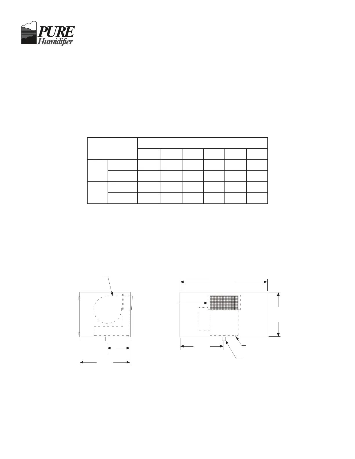
Optional Blower Pack Dimensions
Fig. 5
Blower Pack weight is 60 lbs (27.2 kg)
* Blower requires a separate 120/1 circuit (by others)
296/435 CFM Fan
120/1/60*, 2.17 amps
1/15 HP
7.75”
(19.6)
17”
(43.18)
29.50”
(74.93)
15”
(38.1)
14.75”
(37.47)
Steam
Discharge
1/4” NPT Drain Connection
Steam Inlet
Front ViewLeft Side View
Table 4
 Loading...