5
Location
The location selected must provide for electrical service,
cold or hot water supply, and sanitary drain.
When selecting a location, try to keep the humidifier
within 10 feet (305 cm) of the duct to avoid unnecessary
heat losses, condensation within the steam supply line
and excessive pressure buildup in the reservoir.
Visible “fog” will saturate and condense when it contacts
objects such as turning vanes, filters, fans, elbows, or
take-offs. The warmer the air, the more easily it will
dissipate the visible steam. The most active and
warmest portion of the duct will provide better mixing of
the steam and air. The injection tube should be
mounted a minimum of 2 feet (61 cm) downstream from
an elbow or other uneven air flow area.
Avoid mounting single-style injection tube(s) closer than
8-10 feet (244-305 cm) upstream of objects that could
become saturated and condense the steam (reference
paragraph above). If the duct layout does not provide a
straight, unobstructed run of 8-10 feet (244-305 cm), a
multiple injection tube system should be considered to
reduce the visible steam travel distance.
For Fast-Pac and Insty-Pac multiple tube assemblies
please consult factory for job specific non-wetting
distances.
Reference Fast-Pac or Insty-Pac O&M’s for full
installation details.
CAUTION: Do not humidify upstream of filters. Consult
factory.
CAUTION: Smoke detectors should not be located
downstream of injection tube assemblies.
Location of Control Sensors
It is important to avoid mounting any control sensors
within the visible steam. The control sensors should be
mounted a minimum of 8-10 feet (244-305 cm)
downstream from the humidifier injection tube. Due to
the temperature rise that exists within the visible steam
dissipation area, thermostats should not be mounted
near the injection tube.
High-limit humidistats should be installed before any
duct obstruction to make sure the humidifier is
interrupted before saturation can occur on the object.
The high-limit should be mounted a minimum of 8-10
feet (244-305 cm) downstream from the injection tube.
Installing the high-limit closer than 8 feet (244 cm) from
the humidifier may cause erratic control.
Mounting
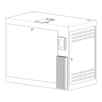
Mounted on the wall. The humidifier should be mounted
dead level in both directions. PURE Humidifier Co.
supplies the wall mounting bracket. Bracket is mounted
to wall studs first. The bracket must be mounted to wall
studs or additional support must be provided in the field.
EC cabinet is then hung on the slip-fit bracket.
Drain Pan Mounting
A drain pan is an additional safety feature which may be
required to be supplied in the field. In a proper
humidifier installation, a drain pan is not required.
However, if the humidifier and injection tube are located
in an area that contains valuable equipment or is a
water sensitive area, PURE Humidifier Co. recommends
the addition of a drain pan under the injection tube. The
drain pan should extend a minimum of 3 feet (91 cm)
downstream from the injection tube. The pan should be
of a size which is sufficient to retain sudden drainage of
the humidifier’s contents. The pan should be drained to
a sanitary drain.
Injection Tube Installation
Single tube units should have the injection tube installed
in the center of the duct. Multiple tube units should have
the tubes staggered within the duct. See Injection Tube
and Flexible Hose Installation on page 8 for details.
Injection tube should be pitched 2 inches (5 cm) per foot
(31 cm), back to the humidifier. If proper pitch cannot
be maintained, or the injection tube is mounted lower
than the humidifier, a drain “tee” will be required.
Install the tube with the steam ports injecting steam up.
NOTE: If narrow ducts (6”/15 cm or less, in height) are
utilized, install the tube with the steam ports injecting
with the air flow slightly (2 o’clock position).
Galvanized steel duct plates are provided to seal the
opening where the tube enters the duct.
Multiple Injection Tube Assemblies
See page 9 for details.
Location & Mounting

 Loading...