8 Service and repair
8-106 Puritan Bennett 800 Series Ventilator System Service Manual
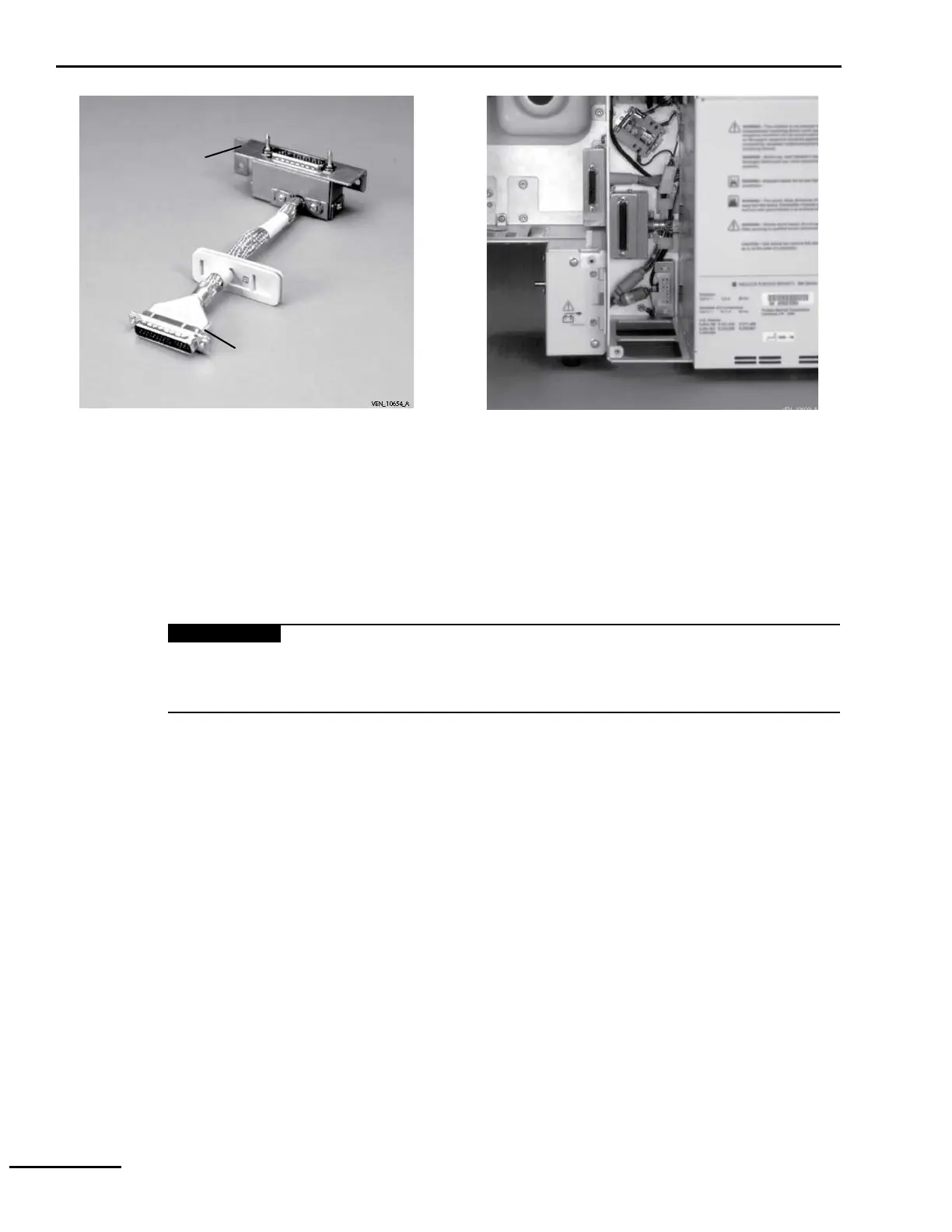
Figure 8-89. Replacing inspiratory blindmate cable
8.15.13.4.2 Installing inspiratory blindmate cable
1 Feed cable’s D-sub connector through inspiratory and power supply compartments.
2 Connect cable to motherboard PCB. Using 1/8-in. (3-mm) flat-bladed screwdriver,
tighten captive screws until snug (Figure 8-86). Do not overtighten.
3 Seat gasket firmly in firewall to create a complete seal. The hole for the cable should be
towards the bottom of the gasket.
To reduce the risk of fire hazard due to oxygen enrichment in the power supply
compartment, make sure the gasket forms a complete seal between the inspiratory module
and power supply compartment.
4 Place bracket over chassis studs and secure with three locknuts. Using 11/32-in.
nutdriver or socket wrench, tighten until snug (Figure 8-89). Do not overtighten.
5 Install BDU housing (Section 8.15.12.2).
8.15.13.5 DC power supply blindmate cable
Replacing the DC power blindmate cable requires #1 Phillips screwdriver with a minimum 6-
in. (15.2-cm) shaft.
8.15.13.5.1 Removing DC power supply blindmate cable
1 Remove BDU housing (Section 8.15.12.1).
2 Using 1/8-in. (3-mm) flat-bladed screwdriver, loosen two captive screws that secure DC
power supply blindmate cable to motherboard PCB connector (Figure 8-86). Disconnect
cable.
3 Allow for access to DC power supply blindmate cable retaining screws:
a. Remove inspiratory blindmate cable (Section 8.15.13.4.1).
b. Remove four chassis-retaining screws from rear of AC panel.
4 Remove two screws that secure cable (Figure 8-90) to chassis. Feed both connectors into
power supply compartment, and remove cable.
Inspiratory
blindmate
cable
To inspiratory
module
To motherboard PCB


 Loading...