22
Steps to testing the DC/DC converter:
Step 1: Check the circuit protection (a circuit breaker or a fuse
cube). Reset the circuit breaker or replace the fuse cube if
blown.
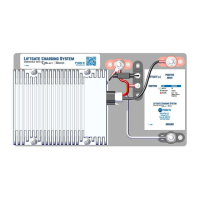
Step 2: Measure the voltage at the liftgate batteries (See V5 on
Figure 22). If higher than 14.0 volts, the charging system is
functioning properly. If no, continue to step 3.
REFERENCE #13
REFERENCE #12
Steps to test power to the DC/DC converter:
Step 1: Look at the Source LEDs on the Select Controller and
ensure that one of them is Solid Green. If no, refer to the
Stinger, Reefer, or Aux Diagnostics sections. If yes, measure
the voltage at the DC/DC Converter Input (+) stud and Ground
(-) Liftgate Battery (Fused) stud (see V1 on Figure 22). Voltage
should be over 10.0 volts. If yes, go to step 2. If no, check
30 amp maxi fuses for the ground, stinger, reefer, and aux. If
fuses are good, and voltage is still below 10.0 volts, replace
the Control Module. If, after replacing the Control Module,
the system still does not function properly, replace the Select
Controller.
Step 2: With a voltmeter, measure the voltage at the ignition input
(see V2 on Figure 22). Should be over 10.0 volts. If yes, skip to
step 3. If no, replace Control Module.
Step 3: With a voltmeter, measure the input and ignition voltages
at the P1020-K Liftgate Charging System Plate Assembly (see
V3 and V4 on Figure 22). Both should be over 10.0 volts. If no,
repair or replace the wires between the Select Controller and
the P1020-K Liftgate Charging System Plate Assembly. If both
voltages are over 10.0 volts, move to reference 13.