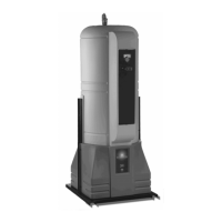
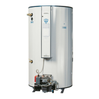
PLATINUM
WATER HEATER
16 PV500-37C 06/12
8. GAS SUPPLY AND PIPING
Verify unit is supplied with type gas specified on rating plate. This unit is orificed for operation up to 2000 feet
altitude. Unit derated 4% per 1000 feet above 2000 feet elevation. Consult Factory for installations above 2000
feet elevation. Conversions must be reviewed and authorized by factory personnel.
8.1 Inlet Pressure - Inlet pressure is measured at the pressure tap located on the side of the main gas cock located
outside the right water heater support leg. The inlet pressure must remain within the minimum and maximum
values while the PLATINUM
®
is at rest, while it is operating at maximum firing rate and while other gas
equipment or appliances are on or off.
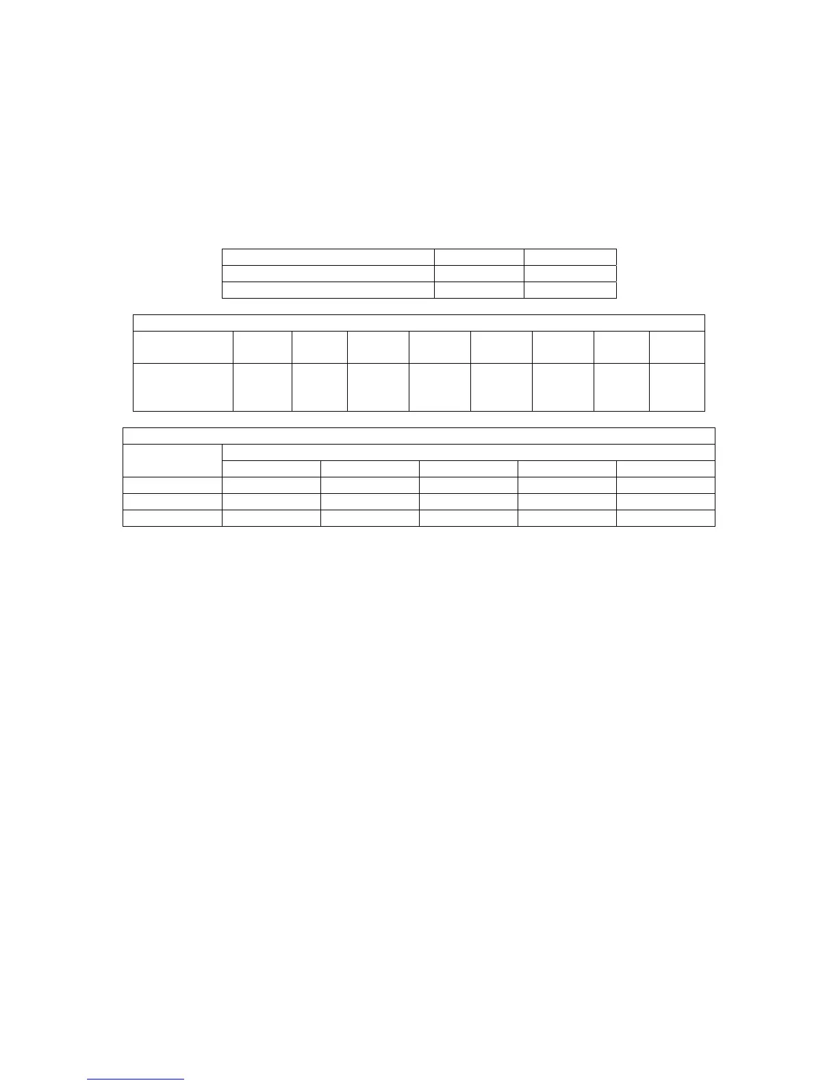
INLET PRESSURE Nat. Gas LP
Max. (Inches-Water Column) 10.5" 13"
Min. (Inches-Water Column) 4.5" 11"
CONVERT FITTINGS TO EQUIVALENT STRAIGHT PIPE
Diameter
Pipe (inches)
3/4" 1" 1-1/4" 1-1/2" 2" 3" 4" 5"
Equivalent
Length of
Straight Pipe
2' 2' 3' 4' 5' 10' 14' 20'
SINGLE UNIT SUGGESTED GAS PIPE SIZE
BTU
INPUT
Distance from Meter (In feet)
0-50' 51-100' 101-200' 201-300' 301-500'
199,000 1" 1" 1-1/4" 1-1/2" 2"
299,000 1" 1-1/4" 1-1/4" 1-1/2" 2"
399,000 1-1/4" 1-1/4" 1-1/2" 1-1/2" 2"
Use the values in “Convert Fittings to Equivalent Straight Pipe” to add the equivalent straight pipe for each elbow
or tee to obtain the total distance from the meter. Use this corrected total distance from the meter for determining
the suggested pipe size in the “Single Unit Installation Suggested Gas Pipe Size” table.
8.2 Appliance Isolation During Gas Supply Piping Pressure Test
1. The appliance and its individual shutoff valve must be disconnected from the gas supply piping system
during any pressure testing of that system at test pressures in excess of 1/2 PSI (3.5 kPa).
2. The appliance must be isolated from the gas supply piping system by closing its individual manual shutoff
valve during any pressure testing of the gas supply piping system at pressures equal to or less than 1/2 PSI
(3.5 kPa).
3. The appliance and its gas connection must be leak-tested before placing it in operation.
8.3 Gas Connection
WARNING: High Voltage Shock Potential - Turn off all electrical service to the appliance when accessing
the gas valve, condensate trap, blower, hot surface ignitor and other components located inside the
lower front and rear panels. After access, close and fasten the lower front and rear panel covers before
restoring electrical service to the appliance. Wires and terminals, such as the gas valve terminals carry
High Voltage (120V). If the electrical service is not turned off, or if the covers are not replaced, and these
terminals are touched, a dangerous shock causing personal injury or loss of life could occur.
1. Safe operation of unit requires adequate gas supply with the required static and dynamic (flow) pressures.
Actual piping selection depends on many variables that must be carefully considered by the gas piping
system designer. Do not select gas pipe sizes based only on the supplied tables. These tables are for use
by the gas piping system designer as a reference in checking pipe size selections.
2. Gas pipe size may be larger than heater connection.
3. Installation of a union between the appliance gas valve and the gas supply piping is suggested for ease of
service.