EasyManua.ls Logo

Pyle PCM30A - User Manual

Pyle PCM30A
23 pages
Print Icon
To Next Page IconTo Next Page
Loading...
InstallinganewAmplifierPCM30a
Step1‐Unboxthenewamplifier(fig1)Setthenewamplifierneartheoldamplifier.
Step2‐Takeapictureofthebackoftheexistingamplifiertologtheoutputconnections.
Step3‐RemovetheRCAInputconnectionfromtheoldamplifierMoveittotheRCA
Inputofthenewamplifier.
ThisRCAmaletomalecordconnectstotheRedRCAfemalefromthemusicunit.
Step4‐Ifconnectingthe70voutputtothenewPCM30Aamplifier,thefarbackrightscrewterminalforthe70vwillbe
the“positivewire,“andthescrew
terminalnexttoitwillbetheCOM“Negative“youwilluse.
KeepinmindtherearemultipleCOMs.YouwillneedtousetheCOMnearesttothe70vonthefarbackrightsideof
theamplifier.
Step5‐Oncethesetwoconnectionsarecomplete,andtheinput
andoutputonthenewamplifierareverified
connected,lookforaSwitchonthebackoftheAmp neartheRed/Whiteinput.ItmustbeswitchedtoAUXPosition.
TheFrontoftheamplifierwillhaveaVolumeknoblabeledMIC2/AUX.Thisvolumecontrolstheinputmusictothe
speakers.
Normallyyouwillwanttosetittoa3or4astonothavethemusictooloud.
Afterthisiscomplete,youcanplugthepowerinontheampandturnthepowerbuttonintotheONposition.Ifyou
donothearmusic,you
mayneedtoadjustthevolumeorthemusicsourcemaynotbeonatthistime.
ForissuespleasecalltechsupportwithUnitedMediaSolutionsat8003738200Opt2
Formusic
inputfeed
COM
8ohm
COM
70V
StandardSetup
BoxSpeakersSetup

Other manuals for Pyle PCM30A

Question and Answer IconNeed help?

Do you have a question about the Pyle PCM30A and is the answer not in the manual?

Summary

McCoys Lumber Install

Installing your UMS LAN connected box

Steps for connecting the UMS LAN system to the network and power.

- System Installation -

General Installation Considerations

General guidelines for wiring, audio outputs, and server communication.

Communication Verification (Required!)

Steps to verify system registration and communication with servers post-installation.

Mounting the system

Guidance on system placement and mounting on a backboard.

AC Power

Instructions for powering up the system via the attached power strip.

Satellite Radio Antenna Installation

Details on connecting and positioning the satellite radio antenna for optimal reception.

Sirius Antenna Aiming Guidelines

System Interface Connections

Explanation of system audio outputs via 3.5mm to phono adapter.

Making the Overhead Connection

Making the Phone Line;Modem connection

Instructions for connecting the system to an analog phone line via modem.

DSL Filter Installation (Only required if site has DSL)

Guidance on installing a DSL/ADSL filter for proper system operation.

Installation

Simple swap out:

Steps and considerations for selecting a system location.

Audio

Overview

This document outlines the installation, usage, and maintenance procedures for various audio and messaging systems provided by United Media Solutions, including an amplifier, call button interface, music players, and SiriusXM components.

Amplifier (Pyle PCM30a)

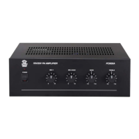
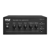
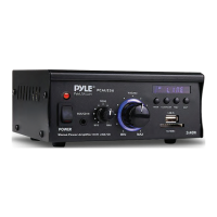
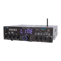
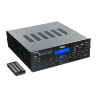
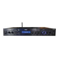
The Pyle PCM30a is an amplifier designed to manage and distribute audio signals for overhead music and messaging systems. It features multiple input and output options to integrate with various audio sources and speaker setups.

Usage Features:

  • Audio Input: The amplifier accepts audio input via an RCA connection, typically from a music unit. This input is used for the main music feed.
  • Microphone Inputs: It includes MIC-1 and MIC-2 inputs, likely for paging or announcements, with individual volume controls.
  • Music On Hold (MOH): A dedicated "Music On Hold" input is available, suggesting integration with telephone systems for on-hold messaging.
  • Paging Output: A "Paging Output" is present, indicating its capability to drive paging speakers.
  • Speaker Outputs: The amplifier offers various speaker outputs, including common (COM), 4Ω, 8Ω, 16Ω, 25V, and 70V terminals, allowing compatibility with different speaker impedances and constant voltage systems. The 70V output is specifically highlighted for use with multiple speakers in a daisy chain configuration, where the "positive wire" connects to the 70V terminal and the "Negative" wire connects to the nearest COM terminal.
  • Volume Controls: Separate volume knobs are provided for MIC-1, MIC-2/AUX, BASS, TREBLE, and a master MONO OUTPUT LEVEL, enabling fine-tuning of audio levels and tone. The MIC2/AUX knob specifically controls the input music to the speakers.
  • Power: The amplifier connects to an AC outlet and has a power button to turn it on/off.
  • Input Selection: A switch on the back of the amplifier, near the Red/White input, must be set to the "AUX Position" for the music input to function correctly.

Maintenance Features:

  • Troubleshooting: If no music is heard, troubleshooting involves adjusting the volume, ensuring the music source is active, and verifying all connections.
  • Testing: An alternate audio source (e.g., cell phone) can be used to test the amplifier's functionality independently of the music unit.
  • Connection Verification: Regularly check that all cords are securely connected, especially the RCA input, speaker outputs, and power.
  • Volume Adjustment: Volumes should be adjusted to the manager's request after verifying connections.

This interface facilitates the connection of call buttons to a music system, enabling the triggering of specific messages or actions.

Usage Features:

  • Call Button Connectivity: It allows the connection of call button wiring, with a mechanism to release spring-loaded wire capture for easy insertion.
  • Serial Port Connection: The interface connects to the Music Maestro serial port, using screws for additional support.
  • Message Assignment: Once connected and powered, the system allows for testing buttons to verify proper operation and message assignment.

Maintenance Features:

  • Wiring: Ensure proper insulation stripping (1/4" to 3/8") for call button wiring.
  • Visual Inspection: Verify that no bare copper extends beyond the face of the port to prevent short circuits.
  • Labeling: Label wires with their designated ports for easy identification and troubleshooting.

Music Players (SanDisk Thumb Drive based & SiriusXM)

These systems are designed to provide background music and messaging.

Usage Features:

  • SanDisk Thumb Drive: A preset SanDisk thumb drive stores the music content and is inserted into a dedicated USB port on the music player.
  • SiriusXM Receiver: The SiriusXM system receives music signals via an antenna.
  • Antenna: The SiriusXM antenna needs to be positioned for optimal signal reception, often requiring placement near a window or outside with a clear view of the sky.
  • Power Strip: The systems are typically powered through a power strip, which can be used to power cycle the unit for reboots.
  • Network Connectivity (for some models): Some units are LAN-connected, allowing for channel changes and updates for music and messages.
  • Audio Output: Audio output is typically via a headphone jack (3.5mm cord) that connects to an amplifier.
  • USB Modem: Some systems utilize a USB modem for connectivity verification, requiring a telephone line with dial tone.

Maintenance Features:

  • Thumb Drive Replacement: If music is lost, a replacement preset SanDisk thumb drive can be inserted to restore music.
  • Power Cycling: Rebooting the music PC or system often involves turning off power at the surge protector, waiting a few seconds, and then turning it back on.
  • Antenna Adjustment: For SiriusXM, the antenna needs to be adjusted for good signal reception. The status light on the Sirius radio (solid green for good reception, flashing red for antenna issues) helps in troubleshooting.
  • Signal Indicators: On PC-based systems, software signal indicators (composite/satellite/terrestrial) can be checked to assess signal strength.
  • Cable Integrity: Regularly check the RG6 Coax cord for the SiriusXM antenna for damage or weathering. Re-terminating F-connectors may be necessary.
  • Connectivity Verification: After installation or troubleshooting, contact technical support to verify that the system is communicating normally with the servers.
  • Message Volume Testing: Test message volume to ensure it is balanced with the music.
  • Location Considerations: When installing, consider distance from connection points, airflow/cooling, accessibility, and site personnel preferences. Avoid placing units near heat-generating equipment or in enclosed spaces.
  • Shipping Old Equipment: Ship back old and unused equipment (SiriusXM tuner, modems, surge protectors) using provided shipping labels.

Triggered Message Numeric Keypad

This keypad allows employees to trigger messages within the system.

Usage Features:

  • Message Triggering: Pressing a key on the keypad actuates a message prompt in the software, pauses the music, and plays the message overhead.
  • RJ45 Connection: The keypad connects to the music unit using a Cat 5 extension and an RJ45 adapter.

Maintenance Features:

  • Functionality Test: Test the keypad by pressing a key to ensure it triggers messages correctly.
  • Cable Trace: If the keypad does not work, trace and correct the Cat 5 extension.

General Troubleshooting and Support:

  • Technical Support: For any issues or questions, contact United Media Solutions technical support.
  • Clock-in/Clock-out: Technicians are required to clock-in and clock-out with technical support before and after performing any work.
  • Required Tools: A list of tools is provided for technicians, including RJ11/RJ45 plugs, RG6/F-connectors, crimping tool, wire nuts, headphones, butt-in set, punch down tool, toner/inductive pickup, wire strippers, screws, cordless drill, monitor, keyboard, mouse, and a ladder for roof access.
  • Technician Knowledge: Responding technicians are expected to have a general understanding of sound systems, PCs, and Windows for tasks like loading drivers, configuring network settings, and performing administrative functions.
  • Service Call Hours: Service calls must be run between 8 AM and 5 PM Eastern Time Mon - Fri to ensure technical support availability.

Pyle PCM30A Specifications

Input Impedance IconInput Impedance
AUX input impedance50k-Ohm
MIC 1/MIC 2 input impedance600-Ohm
TEL/PAGE input impedance600-Ohm
Output Specifications IconOutput Specifications
max output power60 Watts x 1
speaker outputs impedance4-Ohm, 8-Ohm, 16-Ohm, 25V, and 70V
monitor output impedance600-Ohm 1V (head phones) and 8-Ohm 1W (speaker)
Power IconPower
power requirement120V AC 60Hz/230V AC 50Hz
power fuse for 110-120VT 2AL 250V
power fuse for 220-240VT 1AL 250V
Weight and Dimensions IconWeight and Dimensions
dimensions10.7 x 3.46 x 8.86 inches (272 x 88 x 225 mm)
weight9.79 lbs (4.44 kg)
frequency response50 Hz to 15 kHz

Related product manuals