EasyManua.ls Logo

Pyle PLCAPE30 User Manual

Pyle PLCAPE30
4 pages
To Next Page IconTo Next Page
Page #1 background imageLoading...
Page #1 background image
Model: PLCAPE30
3 FARAD DIGITAL CAPACITOR WITH RED DISPLAY )
Capacitance .................................……............. 1,200,000 micro farad
Working Voltage ...............................…….….. 21DC
Surge Voltage .......................................……… 24DC
E. S. R. (Equivalent Series Resistance) ..…….. 0.0012 ohm @ 120hz/25
Capacitance Tolerance …………………..…… ±10%
We recommend at least 1 Farad of capacitance per 500 watts of amplifier output. This is a
general rule of thumb and may be adjusted up or down depending on the efficiency and design of the
amplifiers being used. There is no harm in having more than enough capacitance.
DETAILED FEATURES:
a) 4 digital 8 RED display voltage meter that can measure 0.01 DCV range.
b) Blue Light PCB
c) Over voltage limit and low battery voltage limit warning. When the system voltage peeks over
17.5 DCV or LESS than 10 DCV. The buzzer on the PCB will issue an audible noise warning.
d) Reverse pole connecting PCB buzz warning function. If the capacitor is connected incorrectly
by reversing the positive and negative wires during the installation process the PCB will issue
a 45 second noise to warn you.
e) Lowest E. S. R. 24 DCV foil with maximum moment discharge power in lowest E.S.R..
f) Hi-end chrome/black chrome/satin nickel plated finish solid capacitor casing.
Question and Answer IconNeed help?

Do you have a question about the Pyle PLCAPE30 and is the answer not in the manual?

Pyle PLCAPE30 Specifications

General IconGeneral
BrandPyle
ModelPLCAPE30
CategoryAutomobile Accessories
LanguageEnglish

Summary

Detailed Features

Digital Voltage Meter

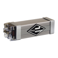
4-digit RED display voltage meter that measures 0.01 DCV range.

PCB Indicator

Features a blue light indicator on the PCB.

Voltage Limit Warnings

Warns with audible noise for over voltage (>17.5V) or low battery (<10V).

Reverse Polarity Protection

Provides a 45-second audible warning if connected with reverse polarity.

Low E.S.R. Foil

Utilizes 24 DCV foil with lowest E.S.R. for maximum discharge power.

Casing Finish

Offers a hi-end finish options: chrome, black chrome, or satin nickel.

Charging the Capacitor

Connection Steps

Connect capacitor terminals to amplifier, then battery ground, then use charging bulb.

Charging Procedure

Use charging bulb/resistor for 30 seconds or until bulb goes out.

Wiring Diagram

Illustration showing correct wiring for charging the capacitor.

Discharging and Installation

Capacitor Discharge Process

Discharge capacitor using a bulb or resistor before removing from system.

Installation Diagram

Diagram illustrating the physical installation and wiring of the capacitor.

Multiple Capacitor Wiring and Warranty

Multiple Capacitor Wiring Diagram

Diagram showing how to wire multiple capacitors with amplifiers and battery.

Warranty Information

Details one-year warranty applicable to products sold in the United States.

Related product manuals