www.PyleUSA.com
3
INSTALLATION
Connect all wiring harness and slide the head unit into the mounting collar
until it clicks into place.
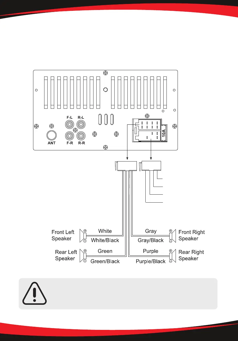
Wiring Connections
ANT: Radio Antenna Socket
FL: Front Left Pre-Amp RCA Output (White)
FR: Front Right Pre-Amp RCA Output (Red)
RL: Rear Left Pre-Amp RCA Output (White)
RR: Rear Right Pre-Amp RCA Output (Red)
10A: 10A Fuse
ACC/ignition (Red)
GND/ground (Black)
ANT/aerial (BLUE)
Power/battery (Yellow)
- +12V DC Negative Ground.
- Only use speakers with 4 ohms impedance.
- The maximum current of the Amp remote trigger is 200mA.