EasyManua.ls Logo

Pylontech US2000B+ - User Manual

Pylontech US2000B+
19 pages
Print Icon
To Next Page IconTo Next Page
Loading...
1 / 19
16BISV0903
Lithium-Iron Phosphate Battery
US2000 (Version B) Product Manual
Information Version: 1.0
Pylon Technologies Co., Ltd.
No. 73, Lane 887, ZuChongzhi Road, Zhangjiang Hi-Tech Park
Pudong, Shanghai 201203, ChinaZip Code: 201203
Tel: 021-51317697
Fax: 021-51317698
Email: service@pylontech.com.cn
Website: http://www.pylontech.com.cn
Question and Answer IconNeed help?

Do you have a question about the Pylontech US2000B+ and is the answer not in the manual?

Summary

1. Introduction

1.1 Features

Lists key features like non-toxic, LiFePO4 cathode, BMS functions, flexible configuration, self-cooling, low self-discharge, wide working temp, compact design.

1.2 Specifications

1.3 Equipment Interface

Product Front Interface Overview

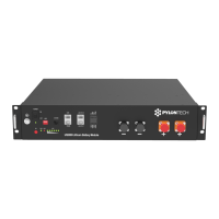
Details the front panel interface including Power Switch, RUN, Start, ADD Switch, Console, CAN, RS485 ports and their functions.

Port Pin Definitions

Defines pin assignments for RJ45 (RS485/CAN) and RJ11 (RS232) communication ports.

Power and Dry Contact Terminals

Describes power terminals for charging/discharging and dry contact terminals for signal input/output.

LED Indicators and BMS Functions

Explains RUN, ALM, Battery Capacity LEDs and lists key BMS management/protection functions.

2. Safe Handling of Lithium Batteries

System Schematic and Safety Symbols

Illustrates system setup and explains crucial safety symbols and warnings for handling batteries.

Required Installation Tools

Lists the tools necessary for installing the battery pack, such as wire cutters and screwdrivers.

Recommended Safety Gear and Accessories

Recommends wearing safety gear like gloves and goggles, and lists included accessories.

3. Installation

Package Contents Verification

Details the items included in the battery package and for connecting to the inverter, ensuring all parts are present.

Installation Location Requirements

Specifies environmental and structural conditions for the installation location, including temperature and humidity.

Cabinet Installation Procedure

Guides on placing battery modules into the cabinet and connecting internal cables.

Power On Sequence Steps

Details the initial steps for powering on the battery system, including cable checks and module activation.

Master Battery Identification and Startup

Explains how to identify the Master Battery Module and initiate the system startup sequence.

Bracket Installation Method

Describes the process of installing the battery using a bracket, including dismantling and assembly steps.

Battery Stacking with Bracket

Illustrates stacking batteries with bracket using location pins/holes and notes maximum stacking capacity.

Sidelong Stacking and Connection Notes

Shows sidelong stacking and confirms cable connections are similar to cabinet installation.

4. Safety Precautions

Pre-Connection Safety Guidelines

Lists essential safety checks and procedures before connecting the battery system, such as power cutoff and wiring.

In-Use Safety Guidelines

Outlines safety measures to follow while the battery system is operational, including maintenance and handling procedures.

Important Reminders

Provides key reminders for users, such as reading the manual, periodic charging, and cable protection.

5. Troubleshooting

Troubleshooting Determination Basis

Defines the initial checks for determining the cause of issues, such as power status and LED indicators.

Preliminary Troubleshooting Steps

Offers detailed steps to diagnose problems related to temperature, voltage, current, and system startup.

Charge;Discharge Issues

Provides specific guidance for resolving problems related to the battery's inability to charge or discharge.

6. Emergency Situations

Handling Leaking Batteries

Details immediate actions and medical attention required in case of battery electrolyte leakage.

Fire and Wet Battery Procedures

Specifies using dry powder extinguishers for fires and procedures for wet or submerged batteries.

Damaged Battery Handling

Outlines the safe handling and return procedures for damaged batteries due to potential hazards.

Overview

The Pylon Technologies Co., Ltd. US2000 (VERSION B) is a Lithium-Iron Phosphate Battery designed for energy storage applications. This product manual provides comprehensive details for its installation, operation, and maintenance.

Function Description

The US2000 (VERSION B) is an energy storage product developed by Pylontech, capable of providing reliable power for various types of equipment and systems. It is particularly well-suited for applications requiring high power, limited installation space, restricted load-bearing capacity, and a long cycle life.

A key feature of the US2000 (VERSION B) is its built-in Battery Management System (BMS). This BMS is responsible for managing and monitoring critical cell information, including voltage, current, and temperature. Additionally, the BMS balances cell charging and discharging to extend the battery's overall cycle life. The system can automatically manage charge and discharge states and balance the current and voltage of each cell.

The battery offers flexible configuration, allowing multiple modules to be connected in parallel to expand capacity and power, meeting requirements for larger capacities and longer power support durations. It adopts a self-cooling mode, which rapidly reduces the overall system noise.

Important Technical Specifications

The US2000 (VERSION B) battery module has several important technical specifications:

  • Nominal Voltage: 48 V
  • Nominal Capacity: 50 Ah
  • Dimensions: 440 mm (width) x 410 mm (depth) x 89 mm (height)
  • Weight: 24 kg
  • Discharge Voltage Range: 45 V to 54 V
  • Charge Voltage Range: 52.5 V to 54 V
  • Peak Discharge Power: 5 KW for 1 minute
  • Peak Charge Power: 5 KW for 1 minute
  • Communication Interfaces: RS232, RS485, CAN
  • Working Temperature Range:
    • Charging: 0°C to 50°C
    • Discharging: -10°C to 50°C
  • Shelf Temperature: -20°C to 60°C
  • Certifications: TÜV / CE / UN38.3 / TLC
  • Design Life: 10+ Years (at 25°C/77°F)
  • Cycle Life: >6,000 cycles (at 25°C, 80% DOD)

The battery uses LiFePO4 as its cathode material, known for its safety performance and long cycle life. The BMS includes protection functions against over-discharge, over-charge, over-current, and high/low temperature conditions.

Usage Features

The US2000 (VERSION B) is designed for ease of use and installation:

  • Non-toxic and Environmentally Friendly: The entire module is non-toxic, non-polluting, and environmentally friendly.
  • Low Self-Discharge: The module has a low self-discharge rate, allowing it to be stored for up to 6 months without charging on a shelf.
  • No Memory Effect: It exhibits no memory effect, providing excellent performance for shallow charge and discharge cycles.
  • 19-inch Embedded Design: Its standard 19-inch embedded design makes the module comfortable for installation and maintenance.
  • Parallel Expansion: Multiple battery modules can be connected in parallel to expand capacity and power, catering to various energy demands.
  • Interface Overview: The front panel includes a Power Switch, RUN indicator, Start button, ADD switches (for addressing in cascaded systems), Console (RJ11 for RS232 debugging), CAN (RJ45 for CAN protocol), RS485 (RJ45 for RS485 protocol), Link Port 0 and 1 (RJ45 for RS485 communication between parallel batteries), Dry Contact Terminal (1 input, 3 outputs), and Power Terminals.
  • Power Terminals: Two pairs of power terminals are provided, each capable of handling charging and discharging functions. These use water-proofed AMPHENOL connectors with a lock button for secure connection and disconnection.
  • LED Indicators: The battery features LED indicators for RUN (green, long lighting during charging, flash during discharging), ALM (red, flashes for alarm, long bright for failure/protection), and a 6-segment capacity indicator (green, each light representing 16.6% capacity).
  • Installation Options: The battery can be installed in a cabinet or stacked using brackets. Up to 4 batteries can be stacked athwart, and one or two batteries can be sidelong stacked.
  • Start-up Procedure: After connecting cables, the system is powered on by switching on all battery modules. The master battery's red button is then pressed to power on, and all battery LED lights will illuminate sequentially, then turn off, indicating proper system operation.

Maintenance Features

The manual outlines several important safety and maintenance guidelines:

  • Safety Gear: It is recommended to wear insulated gloves, safety goggles, and safety shoes when handling the battery pack.
  • Tool Requirements: Basic tools such as wire cutters, crimping modular pliers, and screwdrivers are required for installation. Insulated tools are recommended to prevent electric shock.
  • Installation Location: The installation area must be waterproof, flat, level, free of flammable/explosive materials, maintain an ambient temperature between 0°C and 50°C, have constant temperature and humidity, and minimal dust.
  • Pre-connection Checks: Before connecting, verify the product and packing list, ensure the grid power is off, and the battery is in turned-off mode. Wiring must be correct, avoiding short circuits and incorrect polarity. The battery should not be connected directly to AC power or in series. The system must be well-grounded (resistance < 1Ω), and electrical parameters must be compatible with connected equipment.
  • During Use Precautions: If moving or repairing, the power must be cut off, and the battery completely shut down. Do not connect different types of batteries or use with faulty/incompatible inverters. Disassembly is prohibited unless by authorized personnel. In case of fire, use only dry powder extinguishers.
  • Storage and Charging: For long-term storage, charge the battery every six months to maintain SOC above 80%. After full discharge, recharge within 12 hours.
  • Troubleshooting Steps: The manual provides a systematic approach to troubleshooting, starting with checking if the battery turns on, then observing the ALM light, and finally verifying charge/discharge functionality. It covers issues related to temperature, current, high/low voltage, and provides solutions like relocating the battery, adjusting power supply settings, or charging the battery.
  • Emergency Situations: Guidelines are provided for handling leaking batteries (avoid contact, seek medical attention for exposure), fire (use dry powder, move battery to safe area), wet batteries (do not access, contact supplier), and damaged batteries (handle with care, return to Pylontech).
  • Warranty Registration: Users are encouraged to register online for full warranty coverage after installation.

Pylontech US2000B+ Specifications

General IconGeneral
BrandPylontech
ModelUS2000B+
CategoryCamera Accessories
LanguageEnglish

Related product manuals