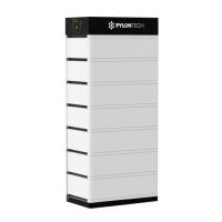
The Pylontech Force-L1 is a 48Vdc Lithium-Ion Phosphate Battery storage system designed for various equipment and systems requiring reliable power. It is particularly suited for applications demanding high power, limited installation space, restricted load-bearing capacity, and a long cycle life.
Function Description:
The Force-L1 system provides energy storage, managing and monitoring battery cells through its built-in Battery Management System (BMS). The BMS tracks cell information such as voltage, current, and temperature, and balances cell charging and discharging to extend the battery's cycle life. Multiple Force-L1 batteries can be connected in parallel to expand capacity and power, meeting requirements for larger energy storage and longer power support durations.
Important Technical Specifications:
- Cell Technology: Li-ion (LFP)
- Battery System Capacity: 24.86 kWh
- Battery System Voltage: 48 Vdc
- Battery System Capacity (AH): 518 AH
- Battery Controller Name: FC0048-100
- Battery Module Name: FL48074
- Battery Module Quantity: 7 pcs
- Battery Module Capacity: 3.55 kWh
- Battery Module Voltage: 48 Vdc
- Battery Module Capacity (AH): 74 AH
- Battery Module Cell Series Quantity: 15 pcs
- Battery Cell Voltage: 3.2 Vdc
- Battery Cell Capacity: 37 AH
- Battery System Charge Upper-Voltage: 53.5 Vdc
- Battery System Charge Current (Standard/Normal): 100 A
- Battery System Charge Current (Max.@15S): 110 A
- Battery System Discharge Lower-Voltage: 44.5 Vdc
- Battery System Discharge Current (Standard/Normal): 100 A
- Battery System Discharge Current (Max.): 110 A
- Efficiency: 96%
- Depth of Discharge: 90%
- Dimension (WDH): 6003801380 mm
- Communication: RS485/CAN
- Protection Class: IP55
- Weight: 265 kg
- Operation Life: 15+ Years
- Operation Cycle Life: 5,000 cycles
- Operation Temperature: 0~50°C (Charging), -10~50°C (Discharging)
- Storage Temperature: -20~60°C
- Product Certificate: VDE2510-50, IEC62619 CE
- Transfer Certificate: UN38.3
Component Dimensions:
- Battery Controller: 600×380×150 mm
- Battery Module: 600×380×170 mm
- Battery Bottom Base: 600×380×40 mm
Usage Features:
- Safety: The entire module is non-toxic, non-polluting, and environmentally friendly. It uses LiFePO4 cathode material for enhanced safety and long cycle life. The BMS includes protection functions against over-discharge, over-charge, over-current, and high/low temperatures.
- Flexibility: Features flexible configuration, allowing multiple battery modules to be connected in parallel to expand capacity and power.
- Cooling: Adopts a self-cooling mode to rapidly reduce system noise.
- Self-Discharge: The module has low self-discharge, capable of being stored for up to 6 months without charging while maintaining over 90% SOC.
- Performance: Excellent performance for shallow charge and discharge cycles, with no memory effect.
- Design: Small size and light weight, with a stackable connection design for comfortable installation and maintenance.
- Control Module (FC0048-100) Display Panel:
- System Status LED: Blue indicates normal operation; Orange indicates protection or failure.
- Blue, slow flashing: Power Relay CLOSE, alarm exists but can continue operation.
- Blue, lighting: Power Relay CLOSE, normal.
- Orange, slow flashing: Power Relay OPEN, normal protection (e.g., Over Voltage, Under Voltage), can recover automatically.
- Orange, lighting: Power Relay OPEN, important protection, failure, lost efficacy, or failed to assign address.
- Battery Module Status LED: Blue indicates normal operation; Orange indicates protection or failure.
- Blue, slow flashing: Alarm exists but can continue operation.
- Blue, lighting: Normal.
- Blue, light once: 1-n LED lights on one by one for address distribution.
- Orange, slow flashing: Module offline.
- Orange, lighting: Module protection, failure, etc.
- System Capacity LED: Indicates the system's State of Charge (SOC). Each LED represents 25% SOC.
- Blue, slow flashing: Idle.
- Blue, flashing: Discharge.
- Blue, lighting: Charge.
- LED Button:
- Short Press: Displays the LED panel for 20 seconds.
- Long Press (more than 5 seconds):
- If status LED fast flashes blue, releasing the button sets RS485 baud rate to 115200.
- If status LED fast flashes orange, releasing the button sets RS485 baud rate to 9600.
- Power Switch:
- Switch A (1P): Controls the battery system's controller (ON/OFF).
- Switch B (2P): Main breaker.
- Start Button:
- Normal Start: Press for more than 5 seconds until the buzzer rings to turn on the controller.
- Black Start: If the system is on and the relay is OFF, press for more than 5 seconds to turn on the relay for 3 minutes (conditions apply).
- Communication Terminals:
- RS485 (RJ45 port): For communication between the battery system and inverter.
- CAN (RJ45 port): For communication between the battery system and inverter, and between battery piles (Link port0/1).
- RS232 (RJ45 port): For manufacturer or professional engineer debugging and service.
Maintenance Features:
- Storage: If stored for a long time, batteries must be charged every six months to maintain an SOC of no less than 90%.
- Recharge: Batteries need to be recharged within 12 hours after being fully discharged.
- Abnormalities: Contact the supplier within 24 hours if any abnormality is observed.
- Damaged Batteries: Damaged batteries are dangerous and must be handled with utmost care. They should be packed in their original container and returned to Pylontech or an authorized dealer. Damaged batteries may leak electrolyte or produce flammable gas.
- Emergency Situations:
- Leaking Batteries: Avoid contact with electrolyte or gas. In case of exposure, evacuate the area, rinse eyes with water for 15 minutes, wash skin with soap and water, induce vomiting if ingested, and seek medical attention.
- Fire: Use only dry powder fire extinguishers. If possible, move the battery pack to a safe area.
- Wet Batteries: Do not allow people to access wet or submerged batteries; contact Pylontech or an authorized dealer.