5
WIRING CONNECTION
1. All connections should be soldered and insulated with electrical tape.
2. Be sure to connect the red power input lead to + 12V power terminal after all the
other leads have been properly connected.
3. Run all ground wires to a common ground.
4. After all the connection is completed, press the “RESET” (19) button.
ANTENNA RELAY WIRE
A yellow wire has been provided for relay controlled antenna. The relay will
automatically activate antenna upward when unit is turned on and retract when unit
is turned off.
CAUTION:
Do not hook up yellow wire to motor wire or damage may occur to the unit.
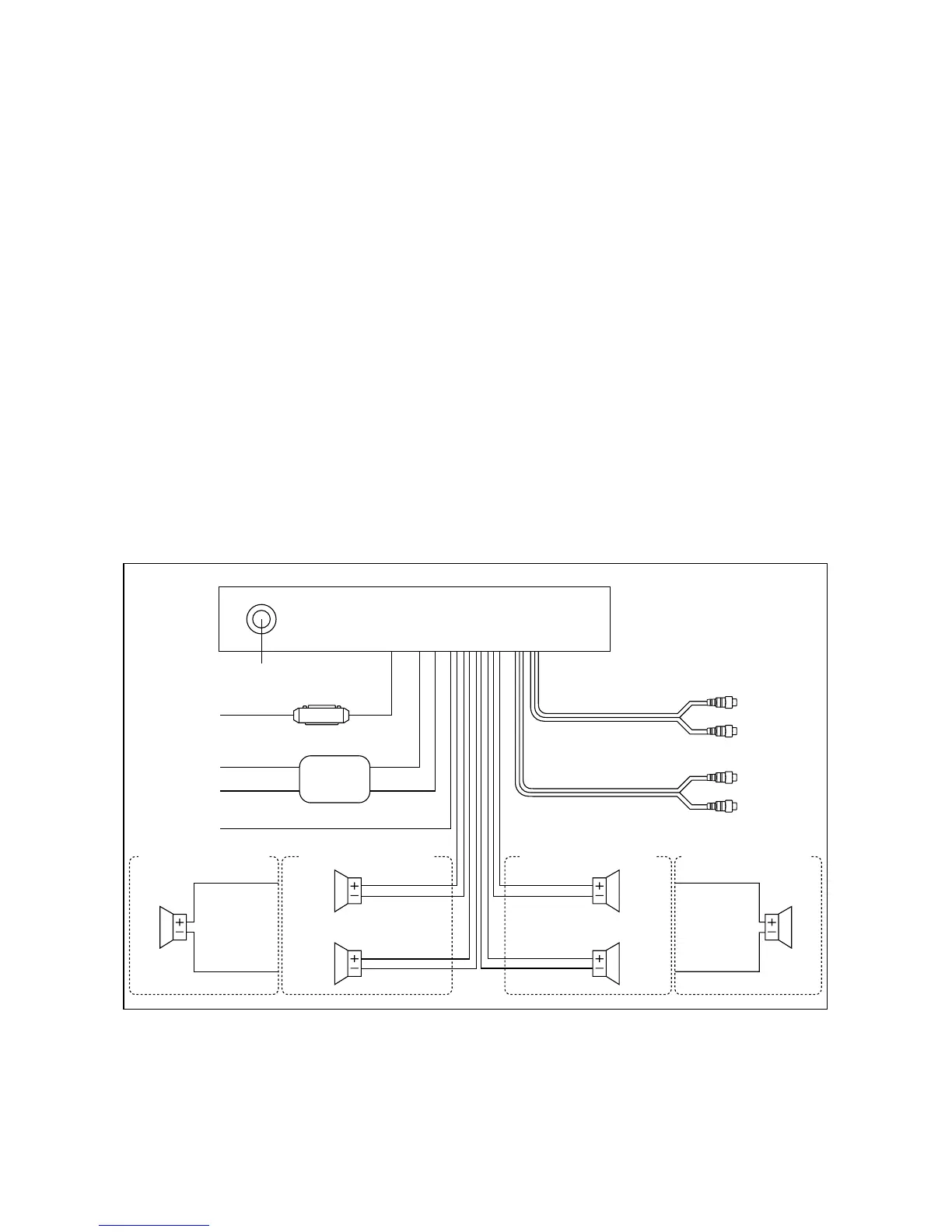
WIRING CONNECTION FOR 4 X 7W OR 2 X 25W SYSTEM
Note:
1. For 2-speakers system, blue, white, green/black and grey/black wire leads are
unconnected and isolated.
2. For 2-speakers system, keep the fader control at center position to maintain the
existing volume level.
MEMORY
BACK-UP
FRONT
Lch SPK.
GREEN
GREEN/BLACK
MAIN UNIT
Rch RED
(FOR RCA LINE OUT VERSION ONLY)
FRONT RCA CABLE
IGNITION
SWITCH (B+)
POWER
ANTENNA
Lch WHITE
REAR
Lch SPK.
RED
GROUND (B–)
PINK
BLACK
CHOKE BOX
YELLOW
Rch RED
Lch WHITE
REAR RCA CABLE
(GREY)
(GREY)
ANTENNA CONNECTOR
BLUE
BLUE/BLACK
4-SPEAKERS SYSTEM
Lch
SPK.
GREEN
BLUE/BLACK
2-SPEAKERS SYSTEM
GREY
GREY/BLACK
WHITE
WHITE/BLACK
4-SPEAKERS SYSTEM
FRONT
Rch SPK.
REAR
Rch SPK.
Rch
SPK.
GREY
WHITE/BLACK
2-SPEAKERS SYSTEM