Do you have a question about the Q CELLS Q.HOME+ESS HYB-G2 and is the answer not in the manual?
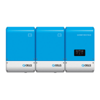
Details the Q.HOME+ESS HYB-G2 device functions and features for safe and proper use.
This manual applies specifically to the Q.HOME+ESS HYB-G2 model.
Download user and installation manuals online; specifications may change without notice.
Explains warning, notice, and information symbols used throughout the manual.
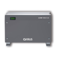
Details the components and parts of the INVERTER unit with a diagram.
Describes the system's standby state before transitioning to active operation modes.
Explains the PV-Auto mode, divided into Weak, Strong, and Both.
Explains monitoring system operation status via internet connection.
Identifies and illustrates the communication ports on the unit.
Instructions for safely cleaning the inverter cover and its components.
General guidance for checking and replacing system components.
Explains the meaning of LED colors on the LCD for system status.
Steps to follow for starting the system after installation.
| Type | Hybrid Inverter |
|---|---|
| AC nominal voltage | 230 V |
| Max. DC power | 7.5 kW |
| Max. input voltage | 600 V |
| Max. PV Input Voltage | 600 V |
| Number of MPP trackers | 2 |
| Battery Compatibility | Lithium-ion |
| Battery voltage range | 40 - 60 V |
| Dimensions | 520 x 400 x 175 mm |
| Weight | 18 kg |
| Operating Temperature Range | -25°C to +60°C |
| Cooling | Natural convection |
| Protection Degree | IP65 |
| Power Output | 5 kW |
| Max. DC Input Power | 7.5 kW |
| Communication | RS485 |