Do you have a question about the QDI P6I440BX/B1S and is the answer not in the manual?
Step-by-step guide for installing the SpeedEasy motherboard and its features.
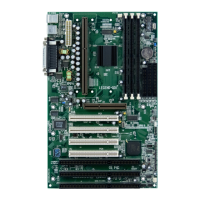
Provides an overview of the P61440BX/B1S green motherboard features.
Details the main hardware specifications and capabilities of the motherboard.
Covers On-board IDE, On-board I/O ports, and advanced system features.
Details BIOS, green functions, and expansion slots available on the motherboard.
Details the PS/2, USB, Parallel, and Serial port connectors on the motherboard.
Instructions for ATX power supply, case connectors like HDD LED, Reset, Speaker, Power LED, Key-Lock.
Explains Green LED connector for system status and the Infrared header (IrDA).
Details fan connectors and wake-up functions for LAN and internal modem.
Covers chassis security, sound connector, expansion slots, and I/O ports.
Instructions for clearing CMOS using JCC and enabling keyboard password power-on with JP2.
Guidelines for configuring system memory, including SDRAM and EDO DIMMs.
Explains System Password and SecurityEasy function for unauthorized access prevention.
Guide on using the FLASH.EXE utility for updating the system BIOS.
Instructions for entering BIOS, loading defaults, and configuring standard CMOS settings.
| Form Factor | ATX |
|---|---|
| Chipset | Intel 440BX |
| LAN | Optional |
| Supported Processors | Intel Pentium II |
| Memory Type | SDRAM |
| Expansion Slots | 1 x AGP, 5 x PCI |
| Storage Interfaces | 2 x IDE |
| USB Ports | 2 |