Do you have a question about the QIACHIP KR2402A and is the answer not in the manual?
Clears all matched remotes. Receiver will not work without paired remotes.
Press learning button 8 times to clear remote data. Indicated by LED 2 flashing.
Relay turns on when button is held, turns off when released.
Press button to turn relay on, press again to turn off.
Press button A to turn relay on, press button B to turn relay off.
Press learning button once, then remote button A, then remote button B.
Press learning button twice, then remote button A, then remote button B.
Press learning button 3 times, then remote button A, then remote button B.
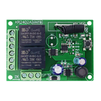
The Qiachip KR2402A is a 2-channel receiver designed for wireless remote control applications, operating within a DC 6-30V power range. This device serves as a versatile component for controlling various electrical loads, such as lights or motors, through remote commands. Its core functionality revolves around receiving signals from a compatible remote control (transmitter) and activating or deactivating its two independent relay channels based on the received commands.
The KR2402A receiver is equipped with two relay channels, each offering Normally Open (NO), Normally Closed (NC), and Common (COM) terminals. This configuration allows for flexible wiring to control different types of loads. The device supports three distinct working modes: Momentary, Toggle, and Latching, providing adaptability for various application requirements.
In Momentary mode, the relay remains activated only as long as the corresponding button on the remote control is pressed. Releasing the button deactivates the relay. This mode is ideal for applications requiring temporary activation, such as opening a gate for a brief period or jogging a motor.
Toggle mode offers an on/off functionality with a single button press. Pressing the remote control button once activates the relay, and pressing the same button again deactivates it. This mode is suitable for controlling lights or other devices where a persistent on/off state is desired with repeated presses of the same button.
Latching mode provides a more advanced control scheme, typically requiring at least two buttons on the remote control. Pressing one button (e.g., A) activates a specific relay channel. To deactivate that channel and potentially activate another, a different button (e.g., B) must be pressed. This mode is particularly useful for applications where multiple states need to be maintained or switched between, such as controlling the forward and reverse motion of a motor, or selecting between different lighting zones. The manual recommends using a remote control with three or more buttons for optimal use in Latching mode, suggesting that a third button (e.g., C) might be used to turn off all active relays.
The receiver's operation is facilitated by a "Learning button" on the circuit board, which is crucial for pairing with remote controls and configuring the working modes. LED indicators (LED1 and LED2) provide visual feedback on the device's status, including power-on, setting mode, and successful pairing.
The KR2402A is designed for ease of integration into existing electrical systems. Its wiring diagram illustrates how to connect the receiver to a lamp, demonstrating the use of the NO and COM terminals for basic on/off control. An external power control light wiring diagram further expands on its versatility, showing how to control a light using an external power supply, with the receiver acting as a switch. The device also supports motor forward and reverse wiring, highlighting its capability to manage more complex loads.
Pairing the receiver with a remote control is a straightforward process initiated by pressing the learning button. The specific number of presses determines the desired working mode. For example, one press for Momentary, two for Toggle, and three for Latching. After initiating the learning process, the user then presses the designated button(s) on the remote control to complete the pairing and mode setting. The LED indicators guide the user through this process, flashing to confirm successful steps.
The device's flexibility in power input (DC 6-30V) makes it compatible with a wide range of power sources, from battery-operated systems to regulated power supplies, enhancing its applicability in diverse environments. The use of standard NO, NC, and COM outputs ensures compatibility with various electrical loads and control circuits.
The KR2402A incorporates a "Reset function" that allows for clearing all previously matched remote controls from its memory. This feature is essential for security purposes, troubleshooting, or when replacing lost or damaged remote controls. To perform a reset, the user needs to press the receiver's learning button eight times. The successful completion of the reset is indicated by LED 2 flashing, after which all remote controls previously paired with the receiver will no longer be able to operate it. This ensures that only authorized and re-paired remote controls can interact with the receiver.
The manual explicitly states that all working modes and pairing procedures are designed to be implemented with QIACHIP remote controls (transmitters). It cautions that there is no guarantee of proper functionality with remote controls from other brands. This highlights the importance of using compatible QIACHIP transmitters for reliable operation and to avoid potential issues related to signal protocols or frequency mismatches.
The LED indicators not only serve during the initial setup but also provide ongoing diagnostic information. For instance, LED 1 and LED 2 being continuously on after power-on indicates that the device is ready for operation or setting. During the setting state, LED 2 specifically acts as the status light, guiding the user through the configuration process. This visual feedback simplifies troubleshooting and ensures that the user can easily monitor the receiver's state.
The robust design, indicated by the wide operating temperature range, suggests that the device is built for durability and reliable performance in various environmental conditions. While the manual does not detail specific physical maintenance, the clear wiring diagrams and operational instructions contribute to proper installation and usage, which are key aspects of device longevity and performance.
| Type | Superheterodyne Receiver |
|---|---|
| Interface | SPI |
| Frequency Range | 2400MHz ~ 2483.5MHz |
| Modulation | GFSK |
| Data Rate | 2Mbps |
| Operating Temperature | -40°C ~ +85°C |