10W HF Linear PA kit assembly 1.00 17
Insert the two left-hand winding ends (3-turns) in their corresponding two holes also.
Pull the wires tight on the underside of the board. Cut the protrusions to 2mm, and scrape the wire
with wire-cutters. This thick wire doesn’t easily allow the soldering iron heat to burn off the enamel,
so scraping the enamel off first helps. The thick wire also absorbs heat easily so be sure to hold
the soldering iron on the joint for at least 10 seconds to be sure of a good connection.
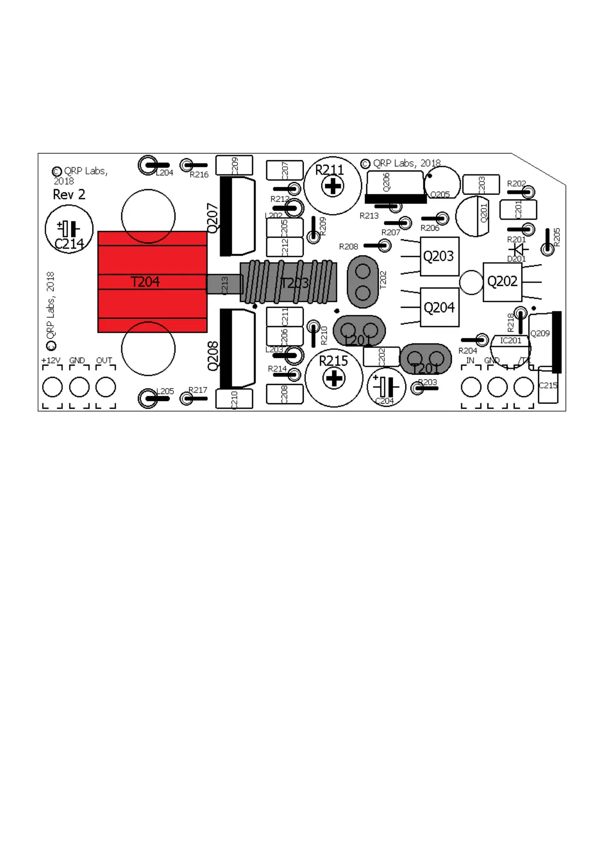
The 3-turn “output” winding can be checked for DC continuity by looking for zero ohms resistance
between the “GND” and “OUT” hole pads at the bottom left corner of the PCB.
There is no way to check the continuity of the 2-turn “input” winding of T204 because there is
already DC continuity through the windings of T203. So careful soldering and an inspection with a
jeweller’s loupe or magnifying glass are the only options available.
 Loading...