10W HF Linear PA kit assembly 1.00 30
3.31 Install heatsink
Depending on your intended application, you may wish to postpone installation on the heatsink, for
example until after you have wired the PA board into your project; or after it has been installed in
an enclosure. An aluminium rear panel may be bolted between the transistors and the heatsink.
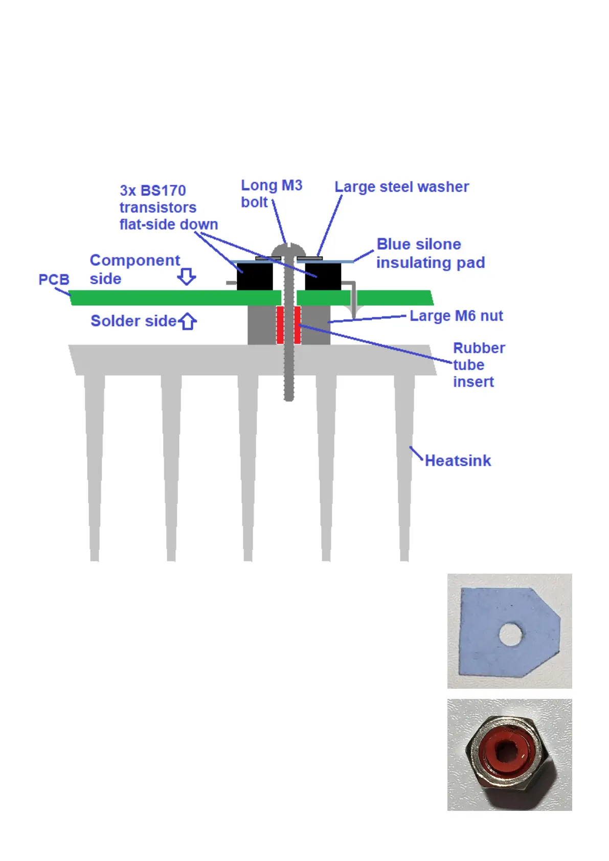
This cross-section diagram indicates the intended mounting of the PA driver stage (three BS170
transistors, pressing them against the PCB and conducting heat via the large M6 nut, to the
heatsink.
1) Cut the blue silicone insulating pad so that it is shaped as shown.
2) Place the pad on top of the PA BS170 transistors Q202, Q203 and
Q204.
3) Thread the large washer onto the 15mm M3 bolt, pass the bolt
through the silicone insulating pad and through the hole in the
PCB, at the center of the three BS170 transistors.
4) Insert the 4mm rubber tube into the M6 nut, as shown. The reason
for the rubber tube is that it keeps the M6 nut central on the bolt;
otherwise it could touch nearby solder connections and cause a
short. Thread this onto the 15mm bolt that was passed through the
PCB, in step 3. This nut will act as a spacer between the PA PCB
and the actual heatsink. It is also a heat conduit from the PCB to
the heatsink.
 Loading...