10W HF Linear PA kit assembly 1.00 7
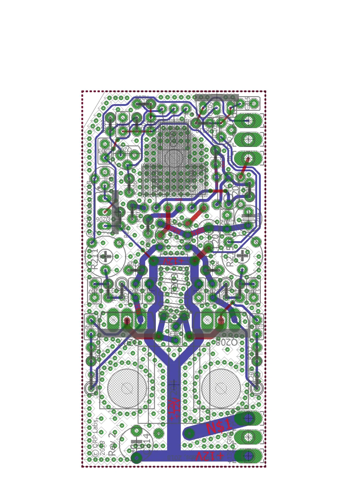
3.2 Trace diagram and parts layout
Red = Top side; Blue = bottom side; Green = pads and vias.
There are only two layers (nothing is hidden in the middle). Not shown in these diagrams are the
extensive ground-planes, on both sides of the board. Practically everything on both layers that isn’t
a RED or BLUE track, is ground-plane! The two ground-planes are connected at frequent intervals
(not more than 0.1-inches) by vias.
 Loading...