NOTE: Photographs in steps 12, 13, 14, 15 and 17 (on this page only) are from the QDX kit,
but the principles are the same!
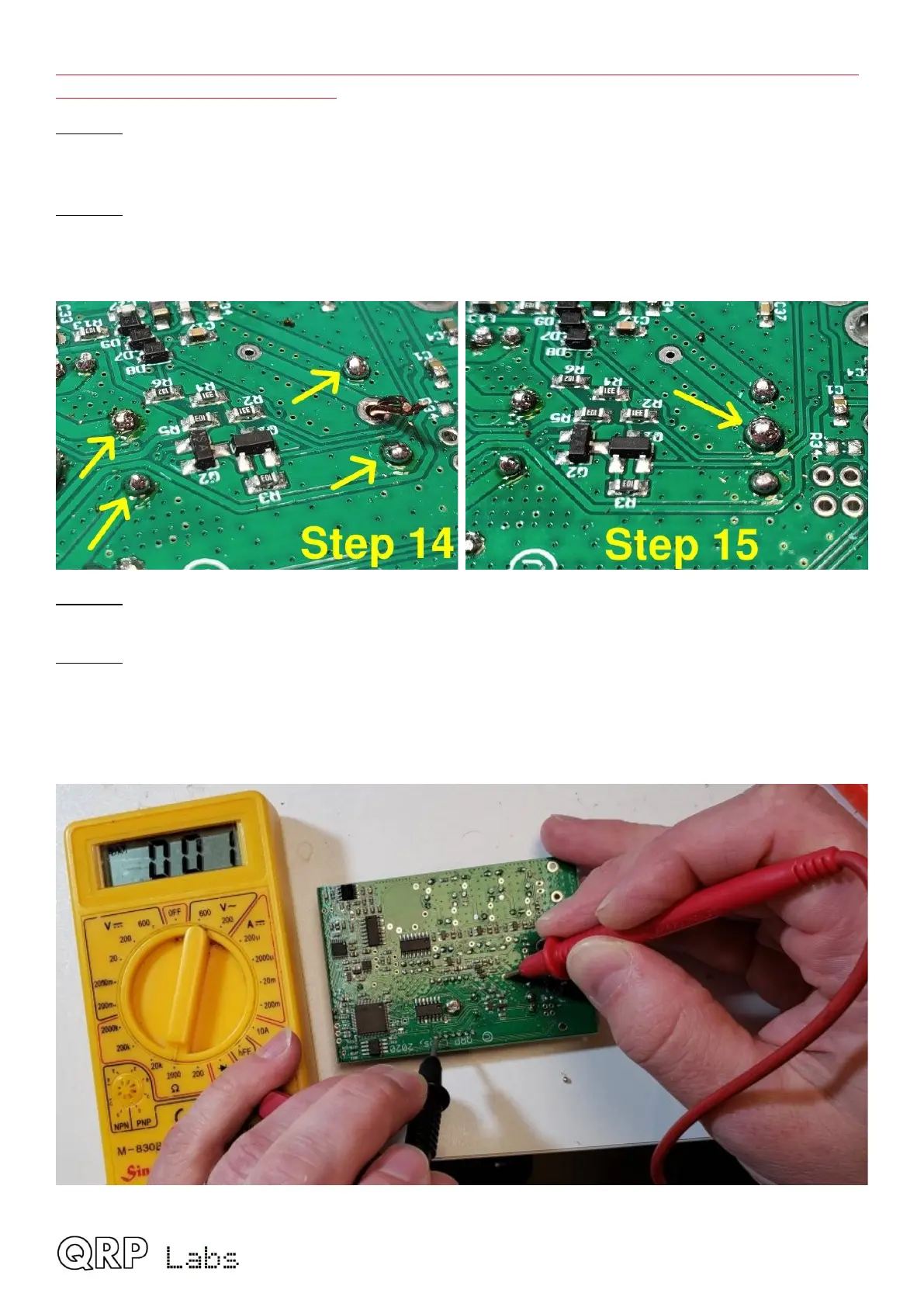
Step 14: Solder the four wire endings. At each pad, hold the soldering iron firmly, apply plenty of
solder, and wait for about 10 seconds. This will ensure a good connection, and any remaining
enamel will be burned away.
Step 15: Finally repeat the procedure with the two center-tap wires that came through the large
center hole. Scrape them, cut them to 2mm, and solder them. Apply plenty of solder and hold the
soldering iron tip to the joint for maybe 15 seconds, to really be sure of a good joint and burning
away any remaining enamel.
Step 16: Check that none of the wires protrude more than 2mm from the surface of the PCB, since
if you are using the optional aluminium enclosure, there are only a few mm clearance.
Step 17: Verify good connections for all five soldered joints of T501 using a DMM set to resistance
or continuity mode. My cheap DMM hasn’t got a continuity mode and I’m using the 2000-ohm
resistance mode; in this mode when there is continuity, the reading on mine shows 001 (not zero-
ohms; this is just a DMM thing, of no significance).
QMX assembly Rev 1.00e 30
 Loading...

