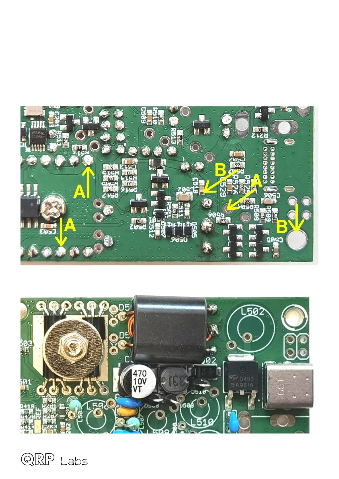
You should see continuity between all the points labeled A in the photo below. Touch the probes
to pairs of these points, to verify continuity.
You should see continuity between the points labeled B also. Touch the two probes to the two
pads labeled B and check for continuity.
Finally, there should be NO connection between A and B. Hold one probe on any A point and the
other probe on a B point. That should read infinite resistance (no continuity).
If any of these tests fail, then you have a soldering problem somewhere, or the wrong wire in the
wrong hole, or some short-circuit somewhere etc.
This is the final appearance of T501 when the installation is complete:
QMX assembly Rev 1.00e 31
 Loading...

