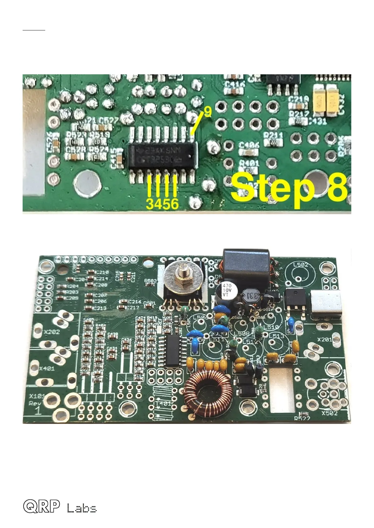
Step 8: Verify the joints are properly soldered, by using a DMM in continuity testing mode (if it has
this mode) or check for zero ohms in resistance mode. On the reverse of the PCB, check for
continuity between pins 3, 4, 5, 6 and 9 of IC3 as shown. You should measure 0 ohms (continuity)
between any pairs of these. If you do not, then there is a mistake somewhere, most probably a
failure to burn away the enamel at one or more of the L401 connections to make a good joint.
Here’s the story so far, including the nicely installed L401 tapped inductor.
QMX assembly Rev 1.00e 34
 Loading...

