16
TD-001536-01-B
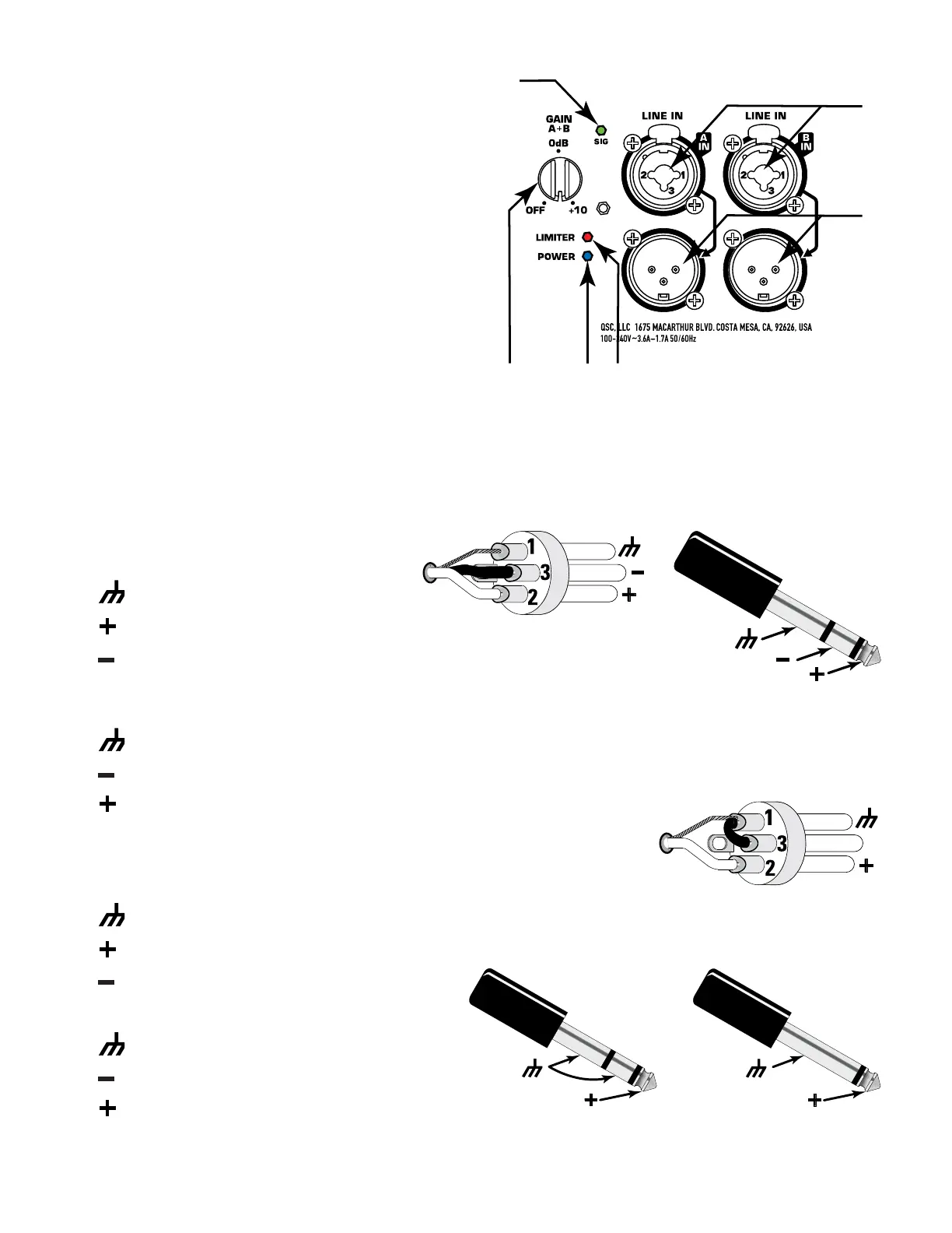
Inputs and Outputs
The KS Series subwoofer amplifier module has two female
XLR/¼-inch combination inputs and two corresponding
pass-through male XLR outputs.
See Figure 18.
1. SIG LED (green) – indicates that a signal is present on
Input A or B or both. When it is not on, there is either no
signal or it is too low to detect.
2. CHANNEL A and B INPUTS – XLR – ¼-inch
combination connector for full-range line-level balanced
or unbalanced audio signals.
3. CHANNEL A and B PASS-THROUGH CONNECTORS
– Use these to daisy-chain full-range audio signals to
other loudspeakers or to other audioequipment.
4. LIMITER LED (red) – comes on when the module
activates its built-in protective limiter. The limiter prevents
damage to the amplifier and transducer—for example, if
the amplifier output signal level is too high or the module
is running too hot.
5. POWER LED (blue) – shows that the amplifier module is turned on.
6. GAIN knob – for adjusting sensitivity of inputs A and B, whose summed signals feed the power amplifier section.
Balanced Inputs
Connect the XLR plug as shown in Figure 19.
1. Shield (ground)
2. Positive
3. Negative
Connect the TRS (Tip-Ring-Sleeve) plug as shown in Figure 20. Do not use a TS (Tip-
Sleeve) plug with a balanced signal.
1. Shield (ground)
2. Negative
3. Positive
Unbalanced Inputs
Connect the XLR plug as shown in Figure 21. (Jumper pins 1 and 3.)
1. Shield (ground)
2. Positive
3. Negative
Connect the TRS or TS plug as shown in Figure 22.
1. Shield (ground)
2. Negative
3. Positive
PUSHPUSH
2
3
– Figure 18 –
– Figure 19 –
– Figure 20 –
– Figure 21 –
– Figure 22 –
 Loading...