11
TD-000521-00-A
DataPorts
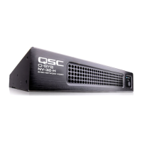
The Q-SYS DataPort I/O card is intended to interface with QSC amplifiers with v1
DataPorts, which is supported on the CX, DCA, PowerLight™, PL2, and PL3 series
amplifiers. All DataPort cables use HD15 connectors. See Figure 18.
IMPORTANT!: These may appear to be common VGA cables, but they are
not. Many of the off-the-shelf VGA cables may appear to work with satisfactory
results. However, it is possible these same cables may not consistently work in a
satisfactory manner and could damage QSC amplifiers they are attached to. The QSC DataPort specification
requires that all 15 connections be present in the cable and that there is proper shielding for the audio
conductor pairs that run to the QSC amplifier. Therefore, QSC recommends the use of QSC DataPort cables
exclusively, which are available in a variety of lengths from QSC. Use of any non-QSC DataPort cable may
voild the Core 510 product warranty.
Connect the QSC DataPort cable from the HD15 connectors on the DataPort Card to the QSC amplifiers. Note that
multi-channel amps can spread accross multiple DataPort IO cards, as long as they are in the same Core or IO Frame.
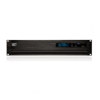
Audio Network Cards and 16-Channel AES3 Input Card (CIAES16)
Audio Network I/O cards provide a bridge between Q-SYS audio networks and products
and systems incorporating 3rd party audio network technologies. All QSC audio network
cards include RJ45 receptacles that accommodate standard data communications cables,
terminated with RJ45 plugs. High capacity AES3 input (16 channel) cards also use RJ45
receptacles. See Figure 19.
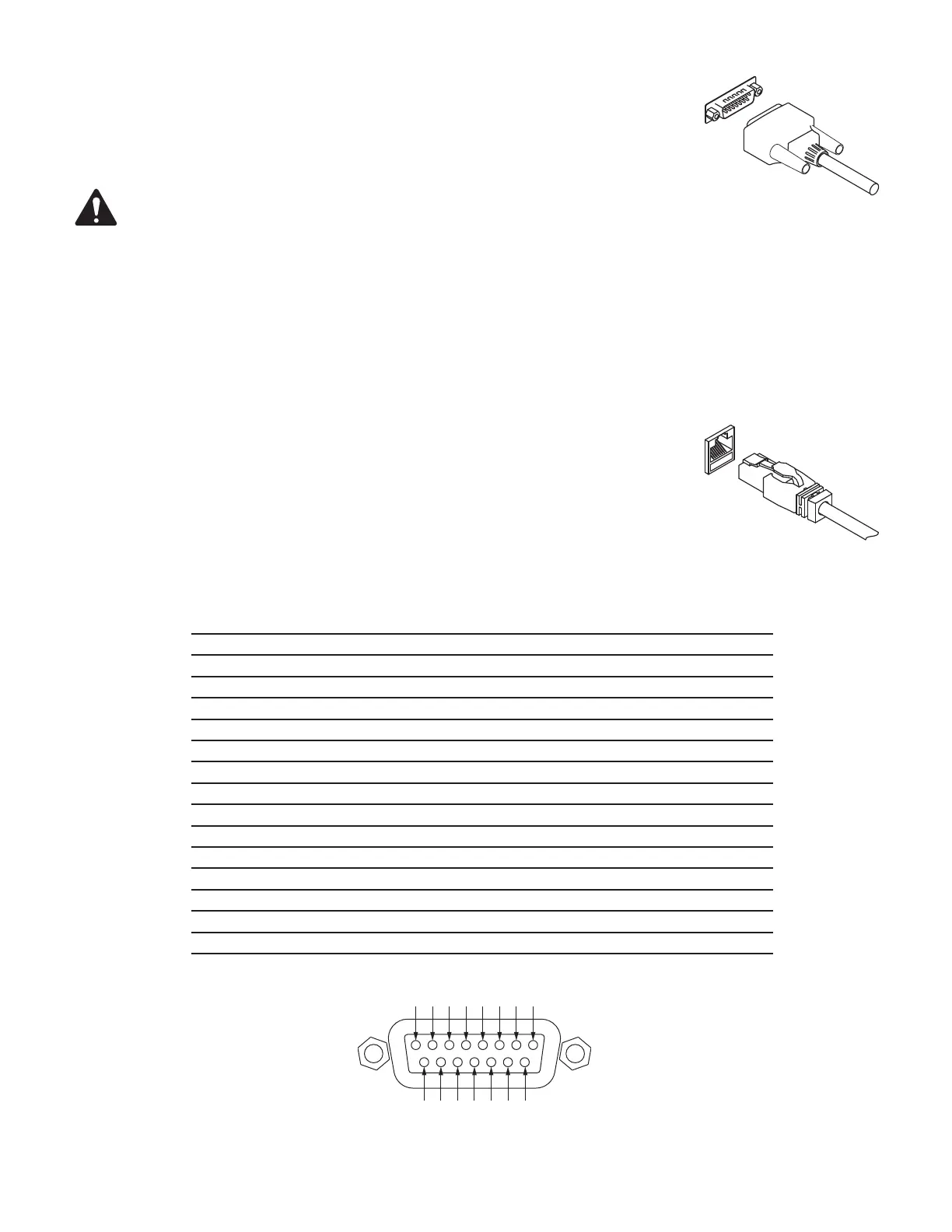
GPIO Pin Assignments
DB15 Pin Signal Name Signal Type Discription
1 RNO Relay Contact Relay - normally open
2 RNC Relay Contact Relay - normally closed
3 GPIO 1 Normal Current GPIO pin
4 GPIO 3 Normal Current GPIO pin
5 POWER Power + 12V DC
6 GPIO 5 High Current GPIO pin -high current capable
7 GPIO 7 High Current GPIO pin -high current capable
8 GND Ground Ground
9 RC Relay Contact Relay - common
10 GND Ground Ground
11 GPIO 2 Normal Current GPIO pin
12 GPIO 4 Normal Current GPIO pin
13 POWER Power + 12V DC
14 GPIO 6 High Current GPIO pin -high current capable
15 GPIO 8 High Current GPIO pin -high current capable
— Figure 18 —
— Figure 19 —
9101112131415
 Loading...