14
TD-000521-00-A
Q-SYS I/O Card Remove and Replace Procedure
This procedure is for Q-SYS Type 2 I/O Cards only. Card installation should only be done by
a trained and qualified technician.
Tools
• Phillips screwdriver
• ESD grounded wrist strap
• 1/4” hex driver/socket (not shown) for replacing Q-SYS I/O cards in slots A through F.
CAUTION!: An ESD grounded wrist strap must be worn throughout the
remove and replace procedure. The end of the wrist strap should be connected
to an unpainted surface on the product chassis such as a ground stud.
1. Disconnect the AC mains power cord from the Q-SYS Core.
2. Connect and put on the ESD grounded wrist strap.
3. Remove the sheet metal screws securing the lid to the Q-SYS Core chassis. Remove
the lid by lifting it approximately 1” at the rear of the chassis while sliding it towards the back.
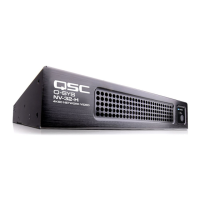
4. Locate the I/O Card to be replaced and remove the ribbon cable (Figure 21) from the card by gently pushing outward
on the cable ejector tabs. The connector should be free of the socket.
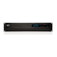
5. Remove the two screws securing the I/O Card Mounting Bracket (Figure 22) on the rear of the chassis. Remove the
bracket.
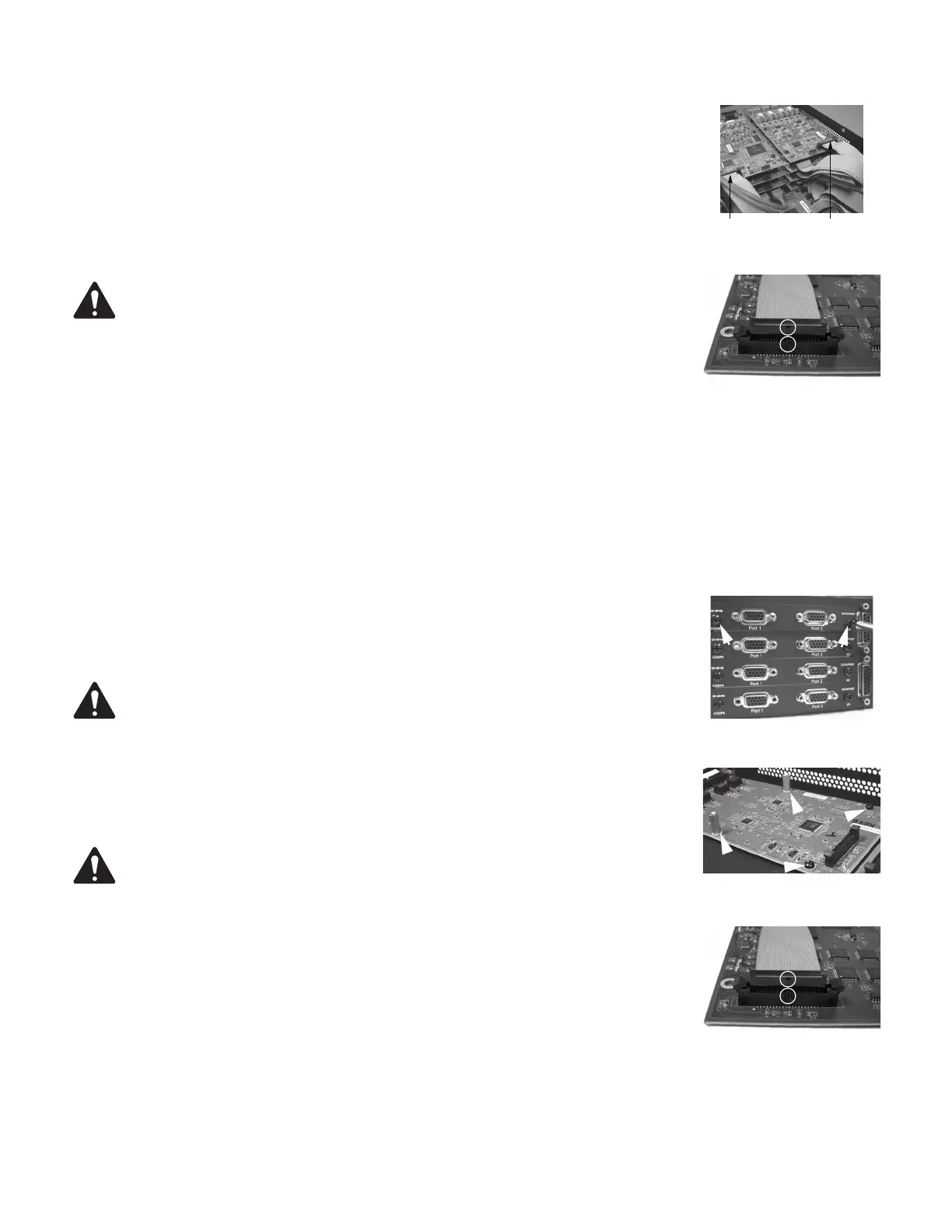
6. Remove the I/O Cards: Refer to Figure 23.
a. For cards in positions G or H, remove the four Phillips head screws securing the card
to the standoffs. Remove the card. If you are not replacing a card in position A through
F, skip to step 7.
NOTE: Figure 23 shows both standoffs and screws for illustration purposes.
The screws are only used on cards in positions G and H. All other cards must
use the standoffs.
b. For cards in positions A through F, remove the cards in positions G and/or H (step 6.a),
then remove the four hex standoffs securing the next lower card, and remove the card.
Continue this until you have removed the card you wish to replace.
WARNING!: Domestic and international safety regulations require that this device
(Q-SYS Cores) be fully configured before power is applied. All eight audio I/O card bays
designated A through H , must include a Q-SYS Audio I/O card and mounting bracket or a
rear plate assembly (RP-1). See (Figure 22). Failure to properly configure this device will
void the warranty.
7. Install the new I/O Card by reversing steps 5 and 6. Be sure to align and secure the I/O
Card Mounting Bracket before tightening the hex standoffs or card-securing screws.
Complete step 7 and 8 for each single level, or layer, of cards as you replace them. Do
not move to the next level of cards until the lower level is properly installed.
8. Reconnect the ribbon cable to the I/O Card, by aligning the tab on the cable connector
housing with the key on the card connector as shown in Figure 24. Gently push down
on the cable connector housing to seat the cable into the card connector. When properly seated, the cable ejectors
will lock in place with the thumb tabs upright.
9. When you connect the ribbon cable to the Core main board be sure that you connect it to the proper connector. The
connectors on the Core main board are identified by the slot letters A through H.
— Figure 20 —
— Figure 21 —
— Figure 22 —
— Figure 23 —
— Figure 24 —
 Loading...