10
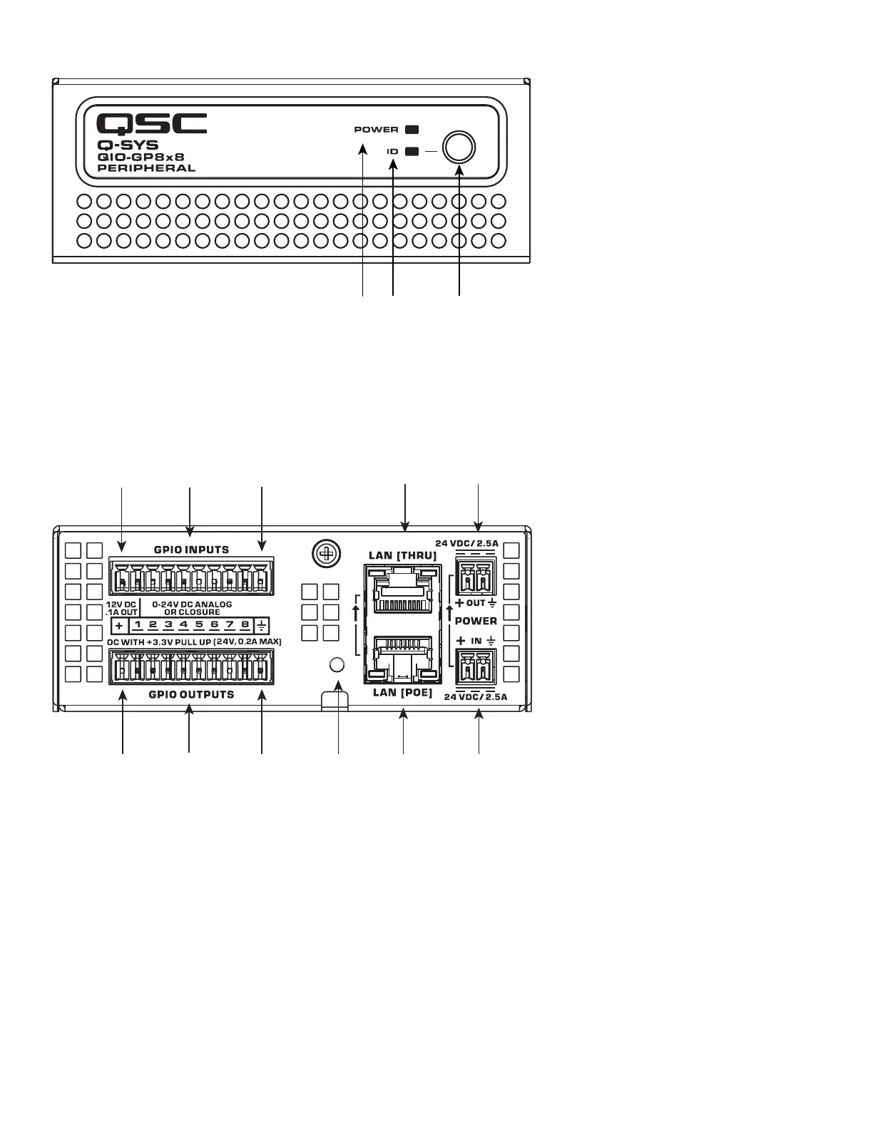
GP8x8 Front Panel
1. Power LED – illuminates blue when the Q-SYS GP8x8 is powered on
2. ID LED – LED blinks green when placed into ID Mode via ID Button or Q-SYS Configurator
3. ID Button – Locates the GP8x8 in Q-SYS Designer Software and Q-SYS Configurator
GP8x8 Rear Panel
1
3
5
6
9
8
1. External Power Input 24V DC 2.5 A – Auxiliary power, 24 VDC, 2.5 A, 2-pin Euro connector.
2. Daisy-Chain Power Output 24V DC 2.5 A - Auxiliary power, 24 VDC, 2.5 A 2-pin Euro connector.
3. LAN [PoE] – RJ-45 connector, 802.3af Type 1 power, Q-LAN.
4. LAN [THRU] – RJ-45 connector, Ethernet daisy-chaining.
5. Device Reset – Use a paperclip or similar tool to restore default network settings and recover factory default settings. Before
attempting a reset, refer to the Q-SYS Help for details.
6. 12V DC .1A Out – For use with General Purpose Inputs and Outputs (GPIO). Uses black connector pins 1 and 11 (not numbered).
7. GPIO Inputs – 8 inputs, 0-24V analog input, digital input, or contact closure (Pins labeled 1–8 equal pins 1–8 in the Q-SYS Designer
Software GPIO Input component). Configurable pull-up to +12V.
8. Signal Ground – For use with GPIO. Uses black connector pins 10 and 20 (not numbered).
9. GPIO Outputs – 8 outputs, open collector (24V, 0.2A sink maximum) with pull-up to +3.3V (Pins labeled 1–8 equal pins 1–8 in the
Q-SYS Designer Software GPIO Output component).
 Loading...