7
Connections and Callouts
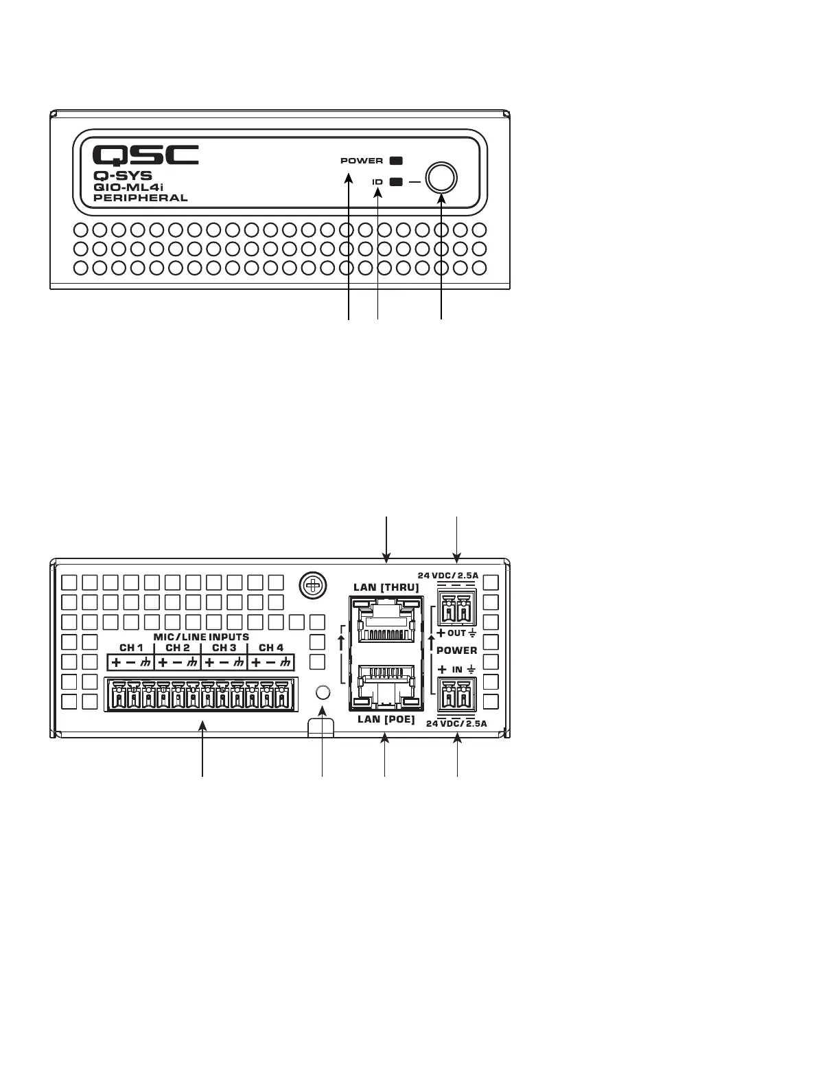
ML4i Front Panel
1. Power LED – illuminates blue when the Q-SYS ML4i is powered on
2. ID LED – LED blinks green when placed into ID Mode via ID Button or Q-SYS Configurator
3. ID Button – Locates the ML4i in Q-SYS Designer Software and Q-SYS Configurator
ML4i Rear Panel
1. External Power Input 24 VDC 2.5 A – Auxiliary power, 24 VDC, 2.5 A, 2-pin Euro connector
2. Daisy-Chain Power Output 24 VDC 2.5 A - Auxiliary power, 24 VDC, 2.5 A 2-pin Euro connector
3. LAN [PoE] – RJ-45 connector, 802.3af Type 1 power, Q-LAN
4. LAN [THRU] – RJ-45 connector, Ethernet daisy-chaining
5. Device Reset – Use a paperclip or similar tool to restore default network settings and recover factory default settings. Before
attempting a reset, refer to the Q-SYS Help for details.
6. Mic/Line Inputs – four channels, balanced or unbalanced, phantom power – orange
 Loading...