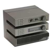
Step 4 - Upgrading the circuit boards.
If you have a stabilized power-supply (+ 57 and – 54 Volt), a function-
generator and a scope you might test the boards before upgrading them. If
you don’t, no problem, you can upgrade the boards without them.
When you connect a dual power supply to the board (+ and – voltage to the
Pcb-connectors, mass to the aluminum heat-sink (don’t use the input mass for
this!), you should read about 110 mA in the – power-line and 120 mA in the +
power-line. This means the power- and driver-transistors are OK.
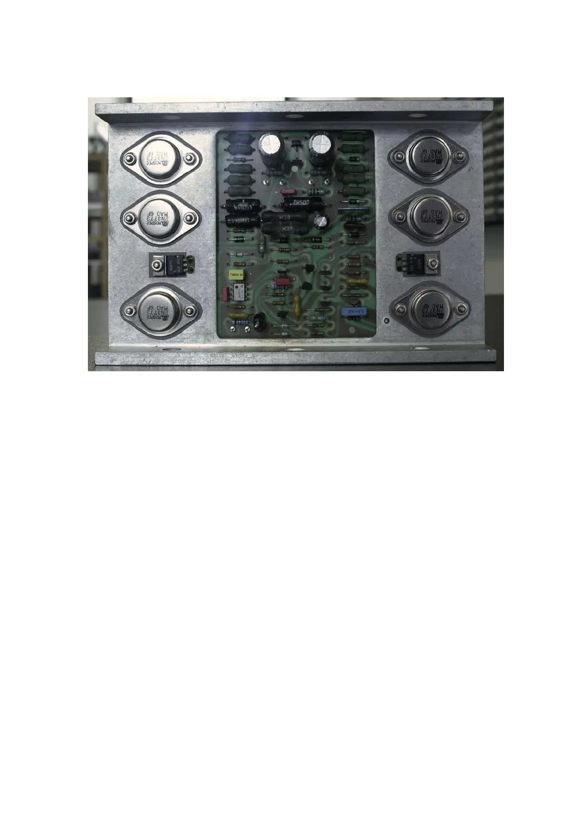
It is a good practice to upgrade the boards one by one. So we can compare
between the boards if we want to see the polarity of capacitors or diode’s or if
something goes wrong.
Replace all the components in the above component-list, except the 6
decouple caps, these are extra components! Solder the small decouple
capacitors on the copper side of the Pcb, do not remove/replace the zeners!
See the picture below for an example. Use the Pcb layout to check the
position of the components, the layouts are copper trackside, not component
side! The issue number of the Pcb is also on the copper side.
 Loading...