Step 2 – Dismantling the 606
• Remove the bottom-cover (Philips n°2, 8 screws including 4 feet, also
two screws on the back Philips n° 1), see exploded view in the
appendix
• Remove the wires from the 2 driver-boards (6 connectors/wires per
board)
• Remove the driver-boards (2x 3 screws)
• Remove the 4 PSU-capacitors and mounting-rings.
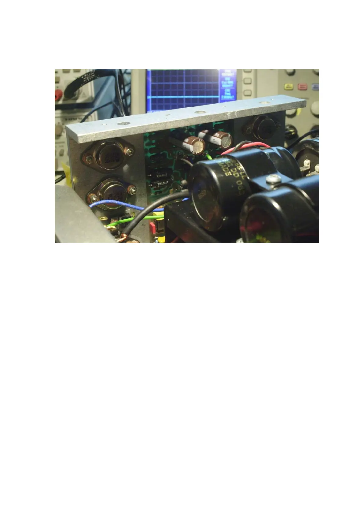
Step 3 - Fitting in the Power Supply capacitors and the connectors
It is important to do these steps in the right order as it makes it more practical
to reach certain components. Use the exploded view as a reference; also
check the T board layout. In the case of a MKII unit, make notes or
photographs during the dismantling.
 Loading...