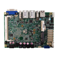
0 Series Use r’s Manual
Jumper Settings
To ensure correct system configuration, the following section describes how to set
the jumpers to enable/disable or change functions. For jumper descriptions, please
refer to the table below.
Table 2 Jumper List
Label Function
JP1 RTC Reset Selection
JP
MPCIE Activity LED Indication
JP4 Backlight Enable Selection
JP
Panel & Backlight Power Selection
JP
T / ATX Power Mo de Sel e cti on
JP
ME F/W Selection
Table 3 JP1 RTC Reset Selection
1
2
Jumpe
2 Open Normal Operation.
1
DIP 2P 1R MALE STRAIGHT TYPE
Pitch:2.54mm [YIMTEX 3321*02SAGR(6T)]
Table 4 JP2 MPCIe Activity LED Indication
1
2
Jumpe
DIP 2P 1R MALE STRAIGHT TYPE
Pitch:2.54mm [YIMTEX 3321*02SAGR(6T)]
Table 5 JP4 Backlight Enable Selection
21
65
Jumpe
light Enable Level = +3.3V
3
Backlight Enable Level = +5V
2
2
4 Backlight Enable High Activ
Backlight Enable Low Activ
SMD 6P 2R MALE TYPE 180D P-2.0mm[PINREX 222-97-03GBB1]
 Loading...