2 COMPONENTS
The Shake Table II components are identified in Section 2. Some of the those components are then described in
Section 2.2.
Caution: Be careful of the moving parts that form the Shake Table II mechanical system.
2.1 Nomenclature
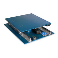
The components listed in Table 2.1 are labeled in Figure 2.1.
ID Component ID Component
1 Stage 9 Sensor circuit board
2 Base plate 10 Right limit sensor
3 DC motor 11 Home position sensor
4 Lead screw 12 Left limit sensor
5 Ball nut 13 Motor leads connector
6 Manual adjustment knob 14 Motor encoder and hall sensors connector (i.e. potentiometer)
7 Linear guide 15 Accelerometer
8 Linear bearing block 16 Accelerometer connectors
Table 2.1: Components
2.2 Description
2.2.1 Stage
The top stage on the Shake Table II is shown as ID #1 in Figure 2.1. It is 18 × 18 inch
2
, or 45.7 × 45.7 cm
2
, and 9.7
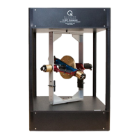
mm thick. The stage has many screw holes that can be used to mount structures and other objects, e.g., Quanser
Active Mass Damper.
2.2.2 Bottom Plate
The bottom support plate, shown in by ID #2 in Figure 2.1, is 24 × 18 inch
2
, or 60.9 × 45.7 cm
2
, and 1.24 mm
thick. The steel linear guides and ball-screw are installed onto this plate. There bottom plate has 4 large screw
holes at each corner and smaller screw holes along the sides of the plate. These can be used to fasten the shake
table onto a ground floor support to prevent the shake table system from moving, or at least reduce the amount of
vibration. Although this is not necessary, it is recommended in order to yield more precise results when, for instance,
measuring acceleration.
2.2.3 DC Motor
The Shake Table II incorporates a Kollmorgen AKM24 brushless 3-phase DC Motor, shown by ID #3 in Figure 2.1.
The motor has a power of 400 W. It is connected to a ball-screw that and drives the ball nut assembly fastened to the
bottom of the shake table platform. The brushless commutation is ensured through three hall sensors with a phasing
of 120 degrees. Some of the motor specifications are included in Table 3.1. More detailed motor specifications are
available in the motor specification sheet [2] under AKM24F.
STII User Manual 6
 Loading...