912-00075-001
Rev
C
09/2020
Bateria
Battery
LED Circuit Board
Tablero de Circuito
Power Supply
Test Switch (EL N Only)
Luz Ready
Black: 120-277V
White: Neutral
Blanco:
Negro:
FI harness
24V DC
Blue
Red/white
Common
CLSR Module
annetnA htooteulB
WIRING DIAGRAM
(LQM CLSR ONLY)
ESQUEMA DEL CABLEADO
(LQM CLSR SÓLO)
(Solamente EL N)
(EL N Only)
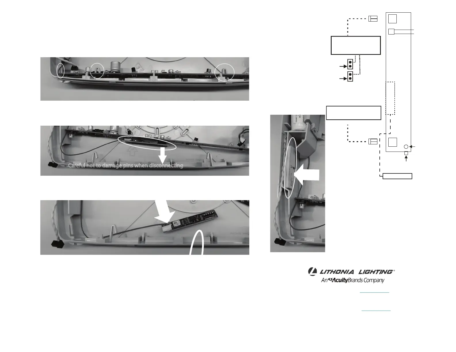
CLSR COMPONENT REPLACEMENT
REEMPLAZO DE COMPONENTES CLSR
1. Disconnect all power to the unit
Desconecte la alimentación a la unidad
2. Disengage snaps and raise lamp board
Desenganchar los broches y levantar el tablero de la lámpara
3. Gently disconnect CLSR module from lamp board by pulling straight away from board
Desconecte suavemente el módulo CLSR de la placa de la lámpara tirando directamente de la placa
4. Gently disconnect antenna wire from CLSR module
Desconecte suavemente el cable de la antena del módulo CLSR
5. Remove antenna from housing (Fig. B)
Retire la antena de la carcasa
6. Reassemble in reverse order
Vuelva a montar en orden inverso
Fig. B
Fuente de Alimentación
SOLUTIONS DE SÉCURITÉ DES
PERSONNES
TÉL. : 800-705-SERV (7378) www.lithonia.com
techsupport-emergency@acui tybrands.com
© Acuity Brands Lighting, inc.
LIFE SAFETY SOLUTIONS
TEL: 800-705-SERV (7378) www.lithonia.com
techsupport-emergency@acui tybrands.com
1993-2020
All Rights Reserved.
Careful not to damage pins when disconnecting
Tenga cuidado de no dañar los pines al desconectar