Chapter 2 General Information
10
Models QT-740 & QT-750 - Operator’s Manual
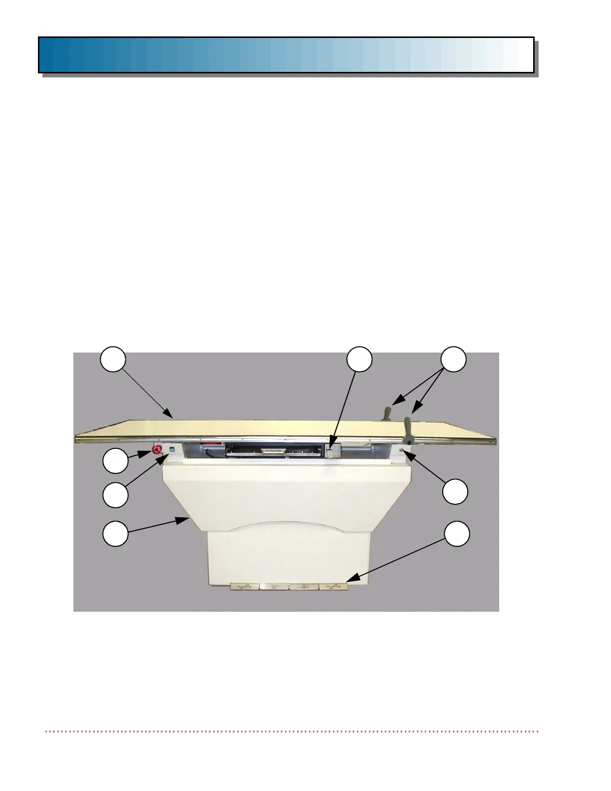
MAIN COMPONENTS
See Figure 1. The radiographic table contains:
1Tabletop
2 Emergency Shut-off Switch (Model QT-750 only)
3 Foot Pedal/FLOAT Push Button Inhibit Switch
4Base
5 Foot Pedal(s) - Float (Model QT-740)
Float, Up and Down (Model QT-750)
6 Float Push Button Switch
7 Patient Handgrips
8 Image Receptor Lock Release Switch
Figure 1. Radiographic Table Main Components
4
3
2
5
8 7
6
1
 Loading...
