Quartz Q16/Q32 System Manual
18 May 2004 Issue 5.00 Page 31
The signal path has been designed to be as short as possible. This reduces the variations in path
length between channels and maintains the overall transparency through the router so important in
broadcast applications.
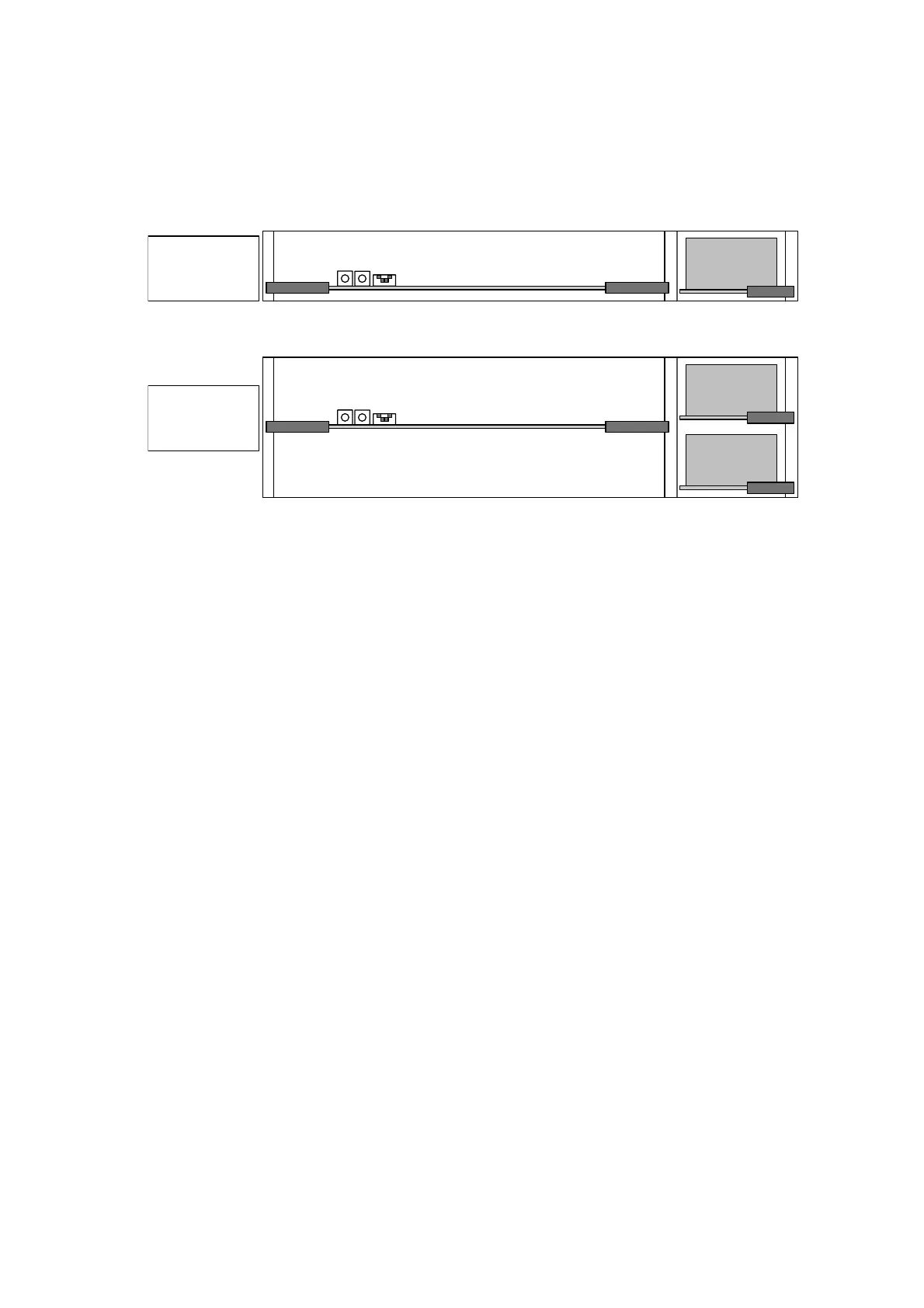
The 1U Q16 frame is shown in schematic form below
Inputs 1-16,
outputs 1-16, and
processor
(PC-222 / PC-215)
PS-0009
The 2U Q32 frame is shown in schematic form below:
Inputs 1-32,
outputs 1-32, and
processor
(PC-222 / PC-215)
PS-0009
Main PSU
PS-0009
Backup PSU
Inputs
The video inputs are terminated in 75Ω.
The main router module contains input buffers that have high input impedance to aid the return loss
performance and an output to drive the crosspoint switch(s). The buffers can operate in two modes:
dc restored for use with composite signals or component signals with sync present. Alternatively, the
buffers can be set to operate in a dc-coupled mode for use with RGB or colour difference signals that
have no sync component. The mode is selected by the user for each block of 8 inputs by jumper links
on the main plug-in router module. This means that the matrix can handle a mixture of composite and
component inputs.
The dc restorer is a feedback sync tip restorer that prevents any crushing of the sync signal.
Matrix
On the Q16 product the crosspoint array is formed from a single IC that is 16x16. On the Q32
product the crosspoint array is formed from two IC’s on matrix sizes up to 32x16, and four IC’s on
matrix sizes up to 32x32.
Outputs
The output amplifiers do not incorporate adjustment controls for insertion gain or high frequency
response as the product has been designed to give unity gain and a flat frequency response.
Analogue Audio Routing
In the Q16 the main audio router card provides a two level 16x16 matrix (Stereo or A1, A2). The card
may be controlled as two levels for split (breakaway) audio or together with the first level (married),
according to how the system is set up. Thus a 16x16 stereo matrix fits in a 1U frame.
In the Q32 two 32x32 matrix modules are used to make a 32x32 stereo matrix and these fit in a 2U
frame. Dual power supplies can be fitted in this frame. More frames can be used for multi-level audio
systems.