LPWA Module Series
BG770A-GL_TE-A_User_Guide 12 / 23
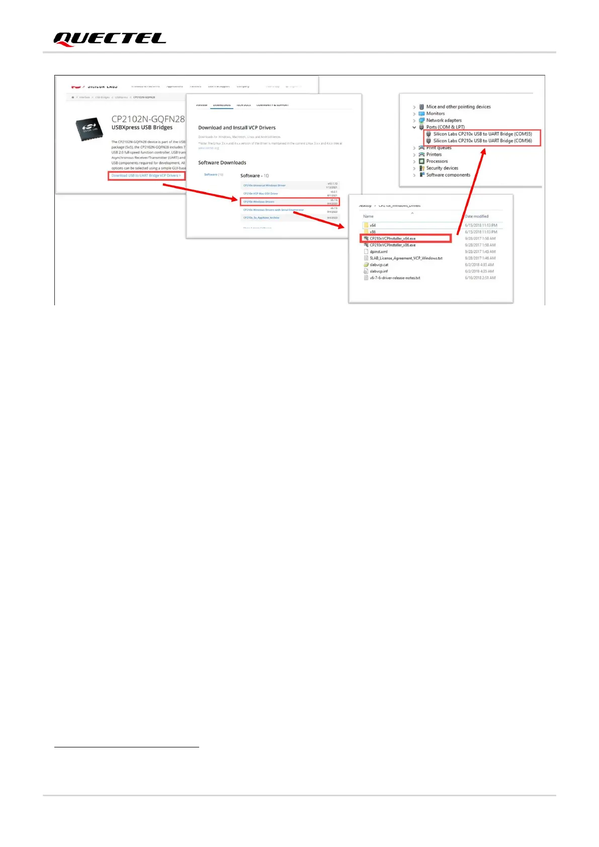
Figure 4: CP2102N Driver Installation
3.2. BTB Connector
The BTB connector is used to connect TE-A to UMTS<E EVB. Most module pins are connected to
BTB1 connector; some pins are connected directly to TE-A’s peripheral circuit or test points; and no pins
are connected to BTB2 connector.
Module signals derived from BTB1 connector are listed below:
⚫ PCM
⚫ I2C
⚫ RESET_N
⚫ PWRKEY
⚫ ADC1
⚫ ADC0
⚫ STATUS_N
To synchronize with the indication LEDs on UMTS<E EVB, an inverter is added to the STATUS output signal of
BG770A-GL, therefore the signal of BTB1 connector is defined as "STATUS_N".
 Loading...