LTE Standard Module Series
DC_IN
MIC29302WU
IN OUT
EN
GND
ADJ
2 4
1
3
5
VBAT
100 nF
470 µF
100 nF
100K
47K
470 µF
330R
51K
1%
1%
4.7K
47K
VBAT_EN
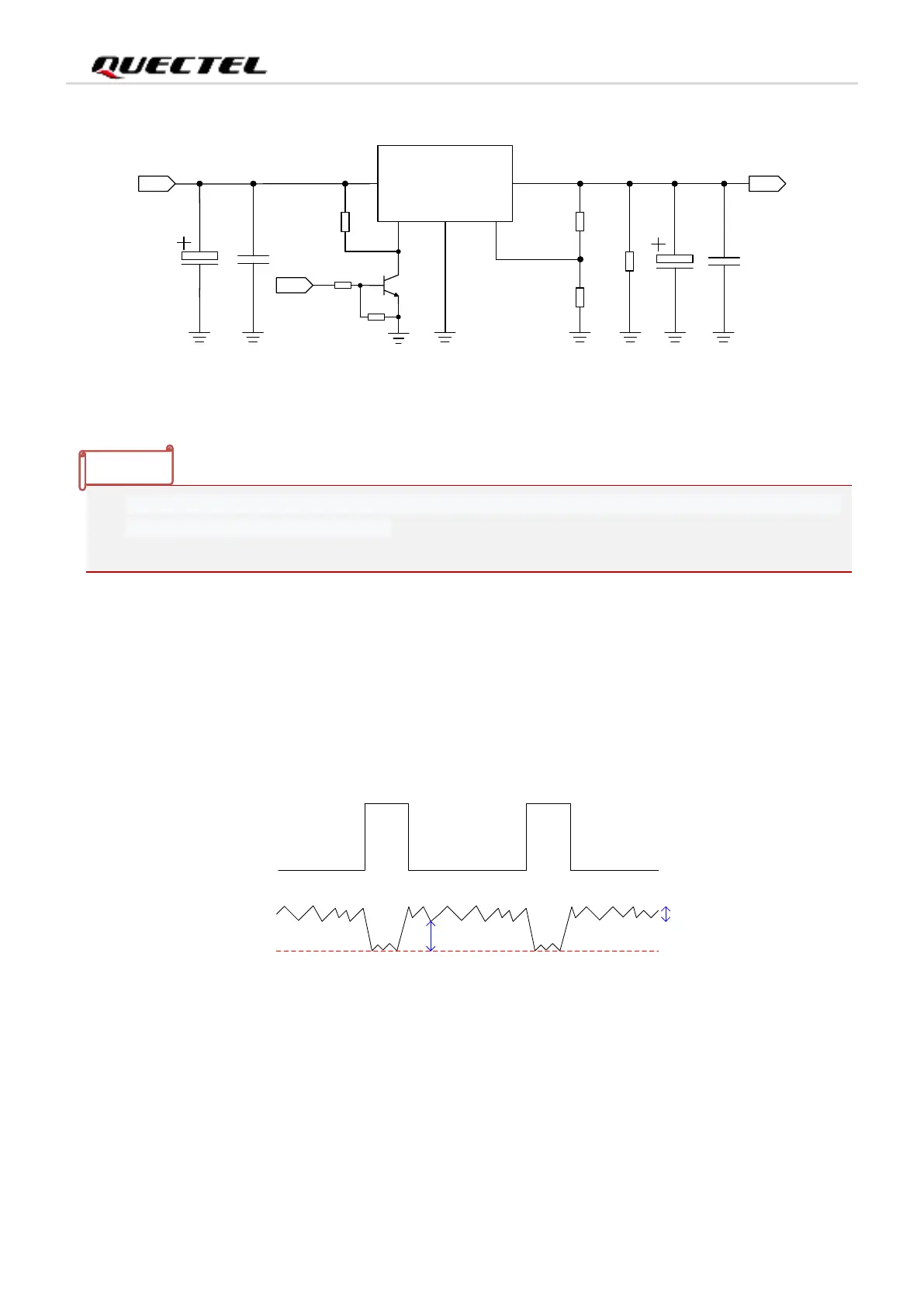
Figure 6: Reference Design of Power Supply
⚫
3.4.3. Requirements for Voltage Stability
The power supply range of the module is from 3.4 V to 4.5 V. Please make sure the input voltage will
never drop below 3.4 V.
VBAT
Ripple
Drop
Burst
Transmission
Burst
Transmission
Figure 7: Power Supply Limits during Burst Transmission
To decrease voltage drop, a bypass capacitor of about 100 µF with low ESR (ESR = 0.7 Ω) should be
used, and a multi-layer ceramic chip (MLCC) capacitor array should also be reserved due to its ultra-low
ESR. It is recommended to use three ceramic capacitors (100 nF, 33 pF, 10 pF) for composing the MLCC
array, and place these capacitors close to the VBAT_BB and VBAT_RF pins. The main power supply from
an external application has to be a single voltage source and can be expanded to two sub paths with star
1. If you use the module that does not support the GSM band, a power supply capable of providing at
least 2 A can be used in the design.
2. It is recommended to design switch control for power supply.