TITLE
PROJECT
Lorry XU
Woody WU
CHECKED BY
DRAWN BY
OF
A
6
5
4
32
1
SHEET
A
B
C
D
123456
D
C
B
Quectel Wireless Solutions
SIZE
VER
1410
1.0
DATE
2019/12/5
EG21-G
A2
Reference Design
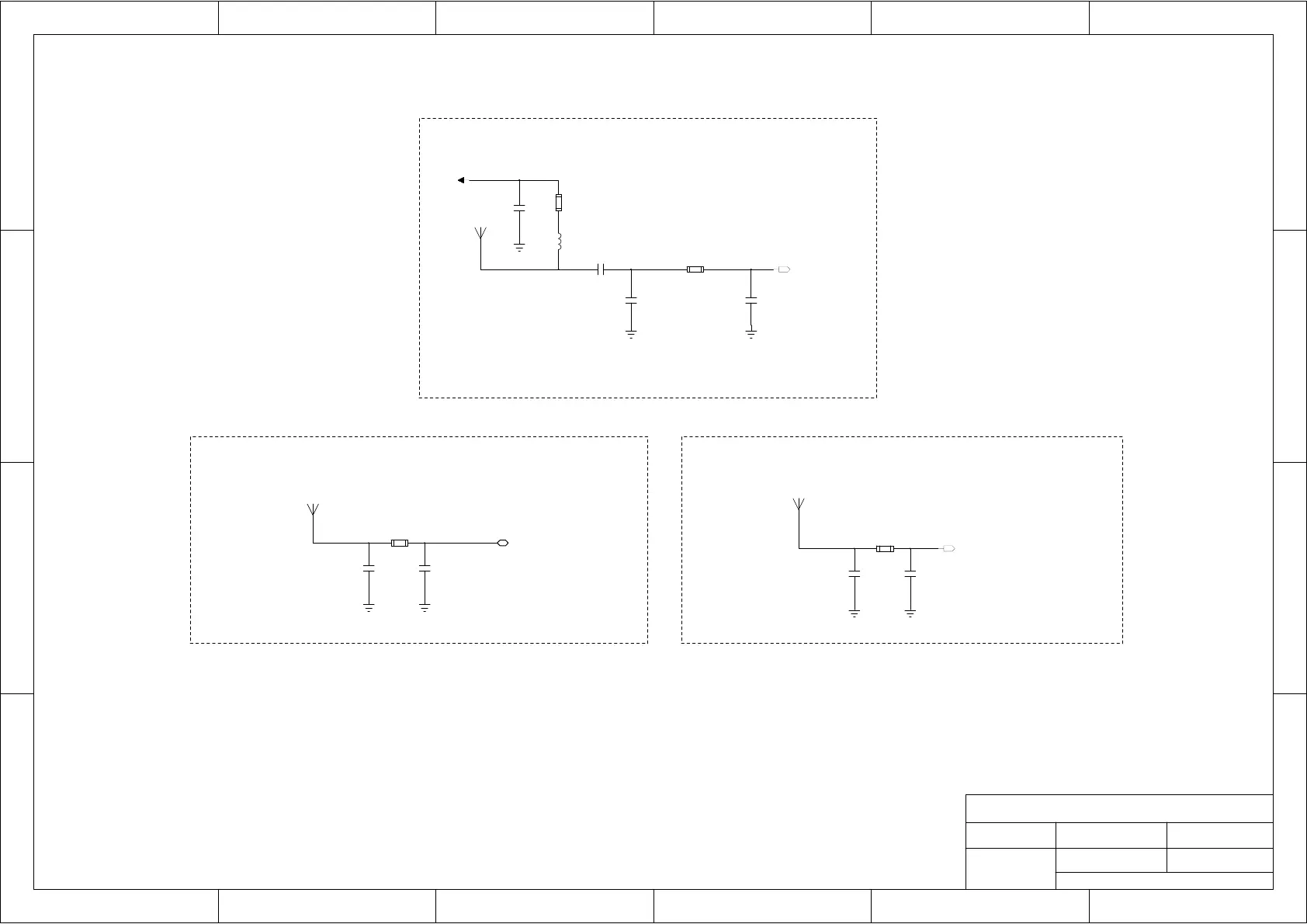
RF and GNSS Designs
Main Antenna Circuit
Diversity Antenna Circuit
GNSS Antenna Circuit
Notes:
1. It is recommended to use PI type main/Rx-diversity antenna circuit, thus ensuring convenient subsequent debugging.
2. The diversity reception function is ON by default. If diversity antenna is not used, there is a need to use AT command to turn off diversity reception. For more details of the AT command, please refer to
3. If an active antenna is selected for the GNSS antenna, a VDD power supply circuit is required; if a passive antenna is selected, the power supply circuit does not needs to be mounted.
Active Antenna
4. The impedance of the RF signal traces must be controlled as 50Ω when routing.
Passive Antenna
The power supply VDD of GNSS needs to be selected according to the requirements of the active antenna.
Quectel_EG21-G_Hardware_Design.
C0801
NM
R0801
0R
J0801
C0802
NM
C0803
NM
R0802
0R
J0802
C0804
NM
L801
47nH
C805
0.1μF
R803
10R
C808
100pF
J804
C810
NM
C809
NM
R0805
0R
[3]
ANT_MAIN
[3]
ANT_DIV
[3]
ANT_GNSS
VDD

 Loading...
