EN
BTQ SERIES INSTALLATION AND USE MANUAL - IT EN - REV001A
30
BTQ series5 - Installation
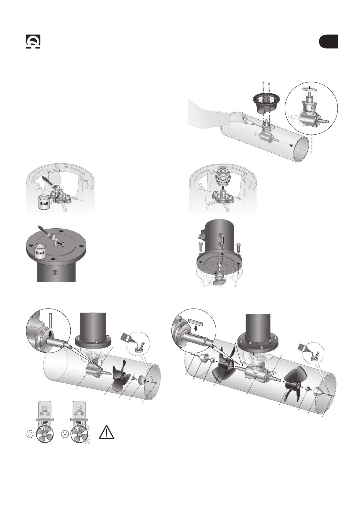
• Grease the terminal part of
the gearleg shaft; t the small
key into its seat.
• Insert the elastic joint in the
terminal part of the gearleg
shaft.
• Insert the motor onto the
elastic joint; fasten it with the
4 screws and washers pro-
vided.
• Grease the terminal part of
the gearleg shaft; t the small
key into its seat.
• Proceed with tting the gearleg with the special seal
gasket.
• For further protection against the entry of water, apply
silicone for nautical use around the point of contact be-
tween ange and tube.
• Fasten everything to the ange using the special screws
and washers.
5.4.2 - BTQ140/180/250/300 Single and double propellers tting
SILICONE
5.4.1 - BTQ140/180/250/300 Gearleg and motor support ange
WARNING: on conclusion of assembly, make sure that
the propeller is exactly positioned at the central point of the tunnel.
LOCTITE
A
B
C
D
F
E
C
Propeller/propellers tting
insert the drive pin or key A into the hole on the gearleg shaft B; assemble the propeller C to the gearleg, making it t in cor-
rectly with the drive pin or key A; x the propeller with the self-braking nut D.
The anode E must be locked with the screw F soaked with building adhesive (such as Loctite).
D
E
F
A
LOCTITE
D
A
B
C
D
E
F
PIN
KEY
 Loading...