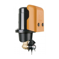
IL THRUSTER
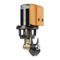
To position the thruster in the tube, find the half-way point
and move to the value shown (
to the right or to the left see
NOTE page 23
) in the table below so that the propeller is
positioned exactly half way along the internal length of the
tunnel.
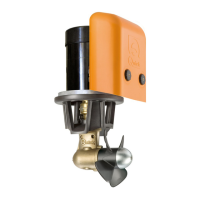
• Use the flange to mark the centre of the holes on the tube.
• Fix the drilling template on the reference points, making
sure they are aligned with precision at the half-way point of
the tube.
N.B. All holes must be exactly aligned with the half-way point
of the tunnel, since tolerance between propeller and tunnel
is minimal.
• Take care that there are no resin residues in the contact
area between flange and tube; this could cause misalign
-
ment. Any resin residues and any other hindrance to correct
contact must be removed by sandpaper.
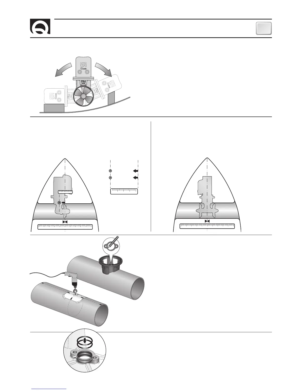
• The thruster can be installed at any angle within 90° from
vertical.
• If the electric motor is positioned of necessity at an angle
of more than 30° from vertical, a special support must be
constructed.
10 2 3 4 5 6 7 8 9 10
10 2 3 4
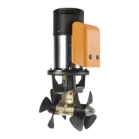
• Insert two o-rings into the special seats inside the flange.
10 2 3 4 5 6 7 8 9 10
• To position the thruster in the tube, find the half-way point.
SINGOL PROPELLER DOUBLE PROPELLER