EN
BTR185 INSTALLATION AND USE MANUAL - REV009A
29
BTR1854 - Installation
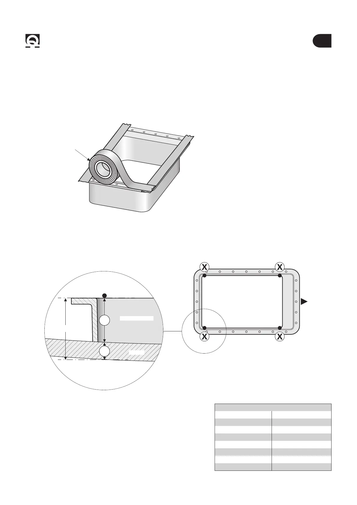
• Protect the gasket with gummed paper tape up to the installation of the propeller to prevent it from getting dirty (Fig. 1A).
4.1 - Counter ange’s installation
Directly access inside the hull, where the thruster will be installed.
The thruster position must enable easy maintenance operations.
Conversion from decimal to fractional inches
3 mm = 1/8” in 35 mm = 1” 3/8 in
5 mm = 3/16” in 45 mm = 1” 49/64 in
8 mm = 5/16” in 80 mm = 3” 5/32 in
8,5 mm = 21/64” in 95 mm = 3” 3/4 in
10 mm = 25/64” in 100 mm = 3” 15/16 in
15 mm = 19/32” in 280 mm = 11” 1/32 in
20 mm = 25/32” in 350 mm = 13” 25/32 in
26 mm = 1” 1/32 in
COUNTER FLANGE
GUMMED
PAPER
Fig. 1B
HULL
COUNTER FLANGE
80/100 mm
• Use a felt-tip pen to mark the counter ange at the four positions
marked with an X on the long sides.
Calculate height using this formula:
h = 80/100mm
-
HT (hull thickness) (g.1B).
BOW
COUNTER FLANGE
Fig. 1A